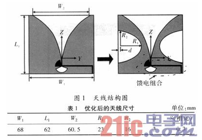
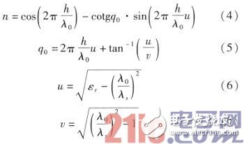
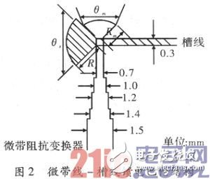
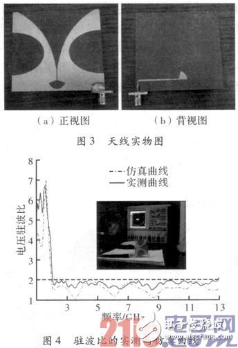
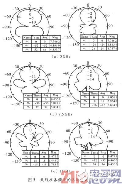
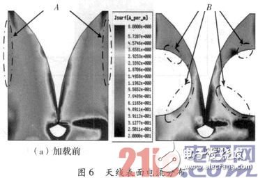
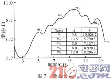
The tapered slot (slot) antenna works based on surface waves propagating along the tapered slot of the antenna, and is a surface wave traveling wave antenna. Compared with traditional ultra-wideband directional antennas such as logarithmic periodic antennas and helical antennas, it has the advantages of symmetrical E-plane and H-plane directional patterns, bandwidth of working frequency, and low cross-polarization. At the same time, it has the advantages of light weight and flat surface. The structure is easy to integrate with microwave circuits. It is the preferred form of ultra-wideband directional antenna and is widely used in ultra-wideband wireless communications, broadband phased array radar and other fields. In the design of the ultra-wideband tapered slot antenna, the desired beam width and directivity coefficient can be achieved by controlling the propagation of surface waves in the tapered groove, that is, the aperture size, length, and taper of the tapered groove antenna are controlled. Parameters such as the shape of the groove, the dielectric constant and thickness of the dielectric substrate, and so on, further affect the impedance and radiation characteristics of the antenna. Generally, two aspects are mainly involved: one is to determine the antenna size and the shape of the tapered slot radiating arm to meet the directional pattern, gain and cross-polarization indicators; the other is the design of the feed structure, mainly from the feeder to the antenna slot line Balanced feed structure requires wide frequency band and low loss. Generally, the length of the tapered slot antenna is about λ0 (λ0 is the wavelength of the lowest operating frequency in free space), and the width is about 0.5λ0. The antenna structure is shown in Figure 1. The gradual radiation curve is an exponential curve, and the curve equation can be given as In order to reduce the influence of the metal patch on the microstrip-slot line balun, the distance between the lower edge of the patch and the lower edge of the antenna is selected to be 16 mm. The dielectric constant εr of the dielectric substrate is selected as 2.65. According to the optimization formula (1), the thickness h is selected as 0.6 mm to obtain The feeding balun is designed as a microstrip line-slotline converter structure. After a given operating frequency, the impedance matching of the balun can be calculated by the following formula Zm=n2·Zs Among them, Zm and Zs are the characteristic impedance of the microstrip line and the slot line respectively; n is the conversion ratio; t is the physical thickness of the dielectric substrate; εr is the relative permittivity of the dielectric substrate. The structure of a microstrip-slotline converter designed in the article is shown in Figure 2. The balun is fabricated on a dielectric substrate with a dielectric constant εr=2.65 and a thickness t=0.6 mm. At the center frequency of 7.5 GHz, the slot The characteristic impedance Z0s of the slot line with an opening width G of 0.3 mm is 109.4 Ω. A 5-section impedance converter is used to achieve the impedance matching between the slot line and 50 Ω. The characteristic impedances of the various transmission lines are 82 Ω, 68 Ω, 61 Ω, 55 Ω and 53 Ω in sequence. The line width calculated by Lincal corresponds to 0.7 mm, 1mm, 1.2 mm, 1.4 mm and 1.5 mm. The radius of the microstrip sector stub is Rm=λgm/4=6 mm, and the radius of the slot line sector stub is Rs=λgs/4=8 mm, where λgs and λgm are the waveguide wavelengths of the slot line and the microstrip line at the center frequency, respectively. Based on the calculated initial value, modeling and simulation in HFSS12, Figure 3 is the actual photo of the antenna, and its input end is connected with a 50 Ω SMA type coaxial connector. A vector network analyzer is used to test the impedance performance of the antenna. As shown in Figure 4, the measured and simulated results are basically consistent. The antenna has a wide impedance bandwidth. In the frequency band of 2 to 13 GHz, the measured antenna standing wave ratio is <2, and the measured results at low frequencies are in good agreement with the simulation results. , The high frequency band is slightly worse, the reason is that the error introduced when cutting the oval gap or welding the SMA joint. Figure 5 shows the far-field pattern of the antenna at 5 GHz, 7.5 GHz, and 11 GHz. It can be seen that the UWB exponentially tapered slot antenna has better directional radiation characteristics. As the frequency increases, the equivalent thickness of the dielectric substrate increases, and the E-plane pattern also has cracks in different degrees. When the equivalent thickness gradually increases to a certain critical value, surface waves that do not participate in radiation will appear on the surface of the antenna, resulting in higher cross-polarization of the antenna at individual frequency points. As shown in Figure 5, the half-power lobe width of the antenna H-plane gain pattern is 60°~140°, and the pattern has good symmetry, which is conducive to wide-angle scanning. The half-power lobe width of the E-plane gain pattern is 30°~66°. It can also be seen that the antenna gain pattern has side lobes in the high frequency band, but its level value is low and the waveform remains better within the range of the main lobe without distortion. Therefore, it does not affect engineering use. The comparison of the current distribution before and after loading the slot is shown in Figure 6. Comparing the two places A and B, the semi-elliptical slot changes the current distribution of the radiating arm, which in turn affects the directivity of the antenna in the low frequency band. The current distribution of the feeding part becomes larger to a certain extent, which makes the gain of the antenna fluctuate in the high frequency range. As shown in Figure 7, in the low frequency range of 2 to 3 GHz, the antenna gain gradually decreases. It can be seen from the figure that in the 3-10 GHz frequency band, as the frequency increases, the antenna gain gradually increases, but when it is higher than 10 GHz, the gain will decrease. This is because in the high frequency band, the radiation area of ​​the antenna energy is close to the feeding part, and the radiated physical conduction area becomes too long, causing part of the energy to be lost in the medium. In addition, in the high frequency range, surface waves crawling on the metal surface and not radiating also affect the antenna gain. Through calculation analysis and physical testing, a new type of ultra-wideband tapered slot antenna is designed. The simulation and actual measurement results show that the antenna has good omnidirectional radiation characteristics and a working bandwidth of 6.5:1. The overall size of the antenna is small and the cross-sectional size is low, which is conducive to the realization of integrated design with other radio frequency circuits, and has high gain, easy to form an array antenna, and has good application value in wireless communication systems. OVNS Mesh Vape Series is so convenient, portable, and small volume, you just need to take them ovns mesh vape bar,ovns mesh vape pen,ovns mesh vape starter kit,ovns mesh vape disposable,ovns mesh vape box Ningbo Autrends International Trade Co.,Ltd. , https://www.vapee-cigarettes.com

out of your pocket and take a puff, feel the cloud of smoke, and the fragrance of fruit surrounding you. It's so great.
We are the distributor of the ovns & vapeak vape brand, we sell ovns disposable vape,ovns vape kit, ovns juul compatible refillable pod, and so on.
We are also China's leading manufacturer and supplier of Disposable Vapes puff bars, disposable vape kit, e-cigarette
vape pens, and e-cigarette kit, and we specialize in disposable vapes, e-cigarette vape pens, e-cigarette kits, etc.