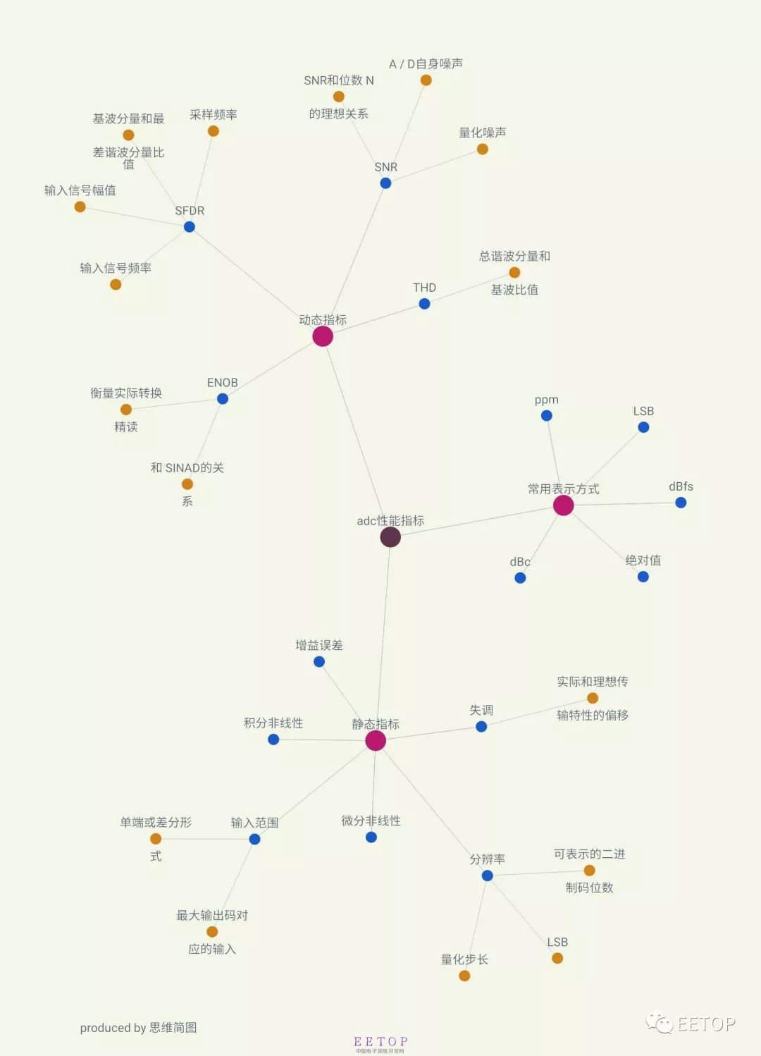
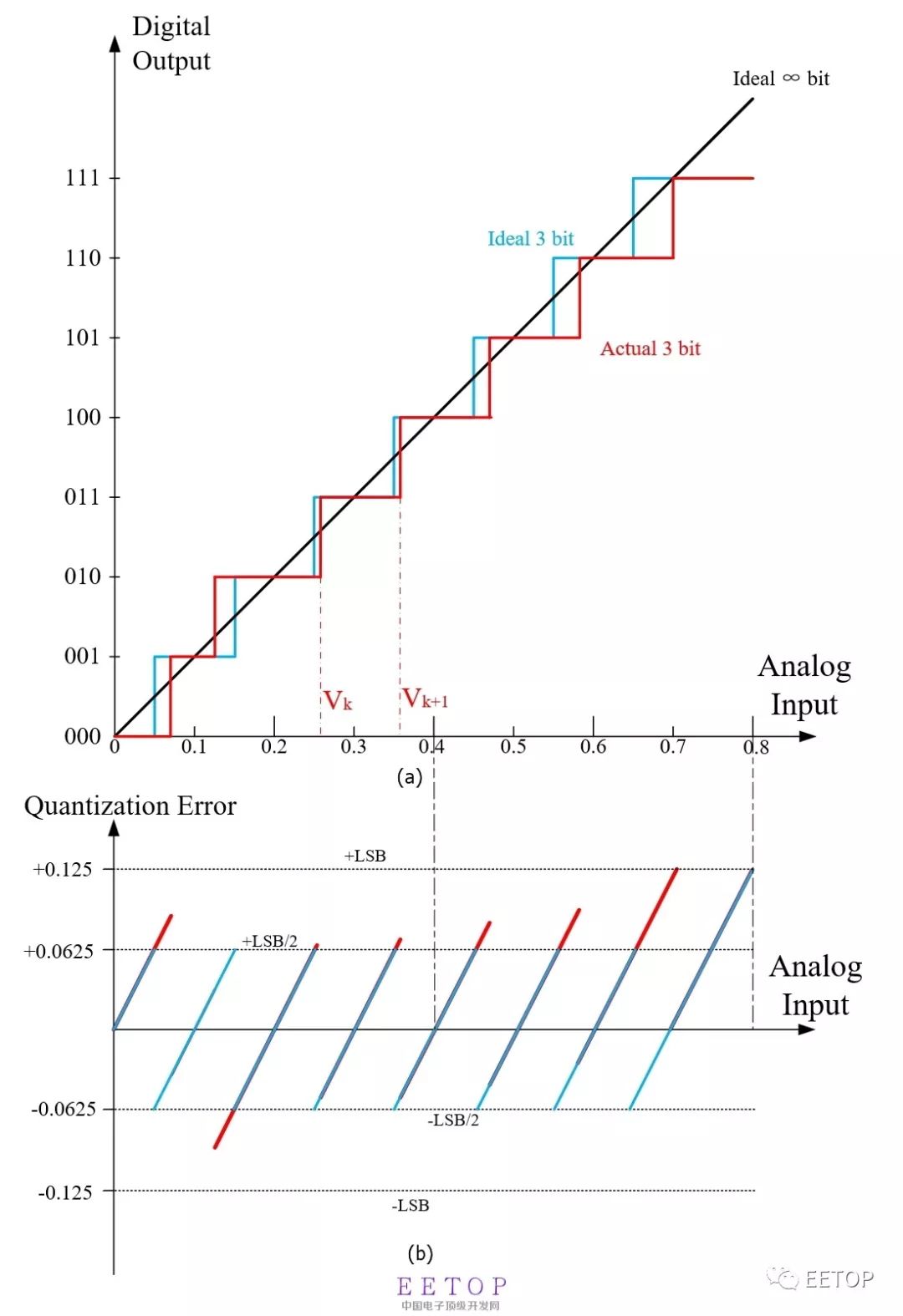
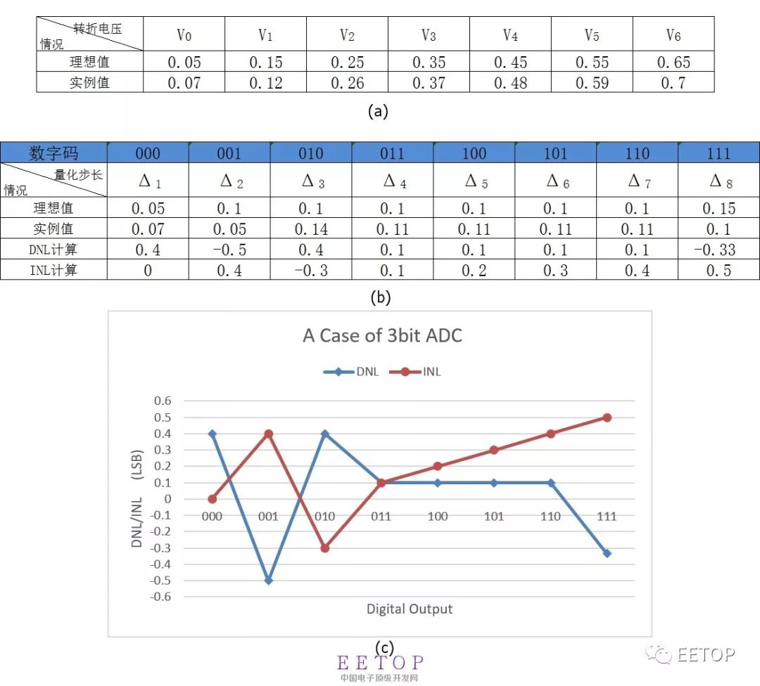
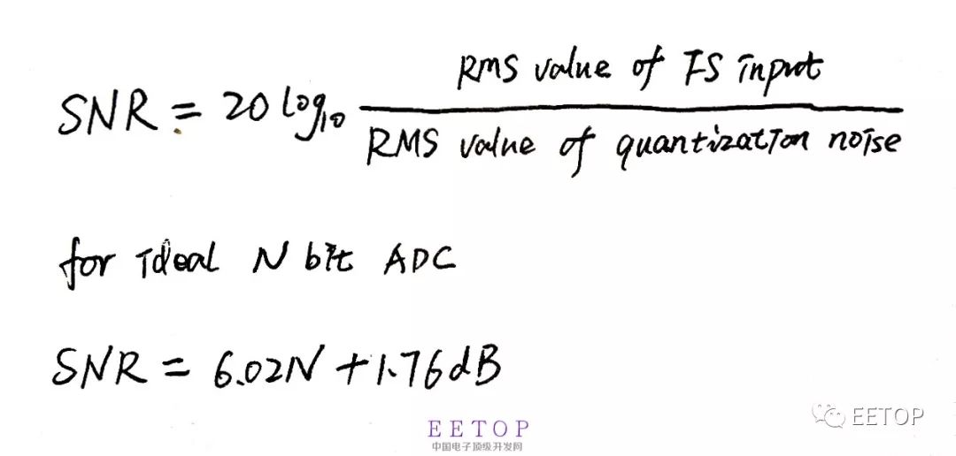
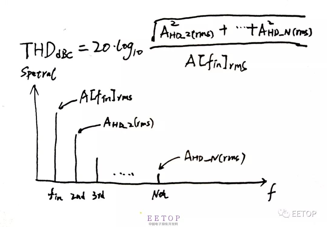
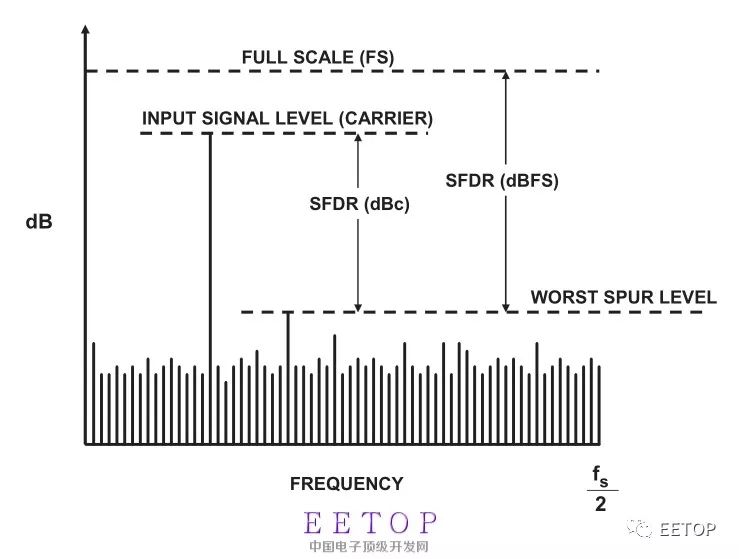
Recently I started to learn SAR ADC. I have had little contact before, so I have a big head to learn, but everything is difficult at the beginning, so just learn a little bit. The development of integrated circuits to this day has benefited from the continuous shrinking of digital circuits under Moore's theorem, the speed has been continuously increased, the power consumption has been continuously reduced, and the area has been continuously reduced. The real world is continuous or chaotic. Data converters (A/D and D/A) act as a bridge between the real world and the binary world. figure 1 First of all, still learn a few important indicators of A/D. There are many parameters to measure the performance of A/D converters. Figure 1 reviews the main indicators. Resolution is the number of bits of a digital signal that the ADC can represent by analog input. Together with the reference voltage (Reference Volatage), it determines the minimum identification voltage that the ADC can distinguish. For example, for a 10-bit ADC, there are only 1024 digital outputs, corresponding to 0~1023 in decimal. Among them, the least bit becomes LSB. The static index can basically be obtained by comparing the ideal and actual transmission characteristics of the ADC. Figure 2(a) shows a schematic diagram whose transmission characteristic is a stepped nonlinear function, where the reference voltage is 0.8V. The abscissa is the analog input voltage, and the output is the digital code output (discrete 2^N code values). Black is the transfer characteristic of infinite resolution. Blue is an ideal 3-bit transmission characteristic, and red is an actual 3-bit transmission characteristic. figure 2 Figure 2(b) is a schematic diagram of the quantization error, the abscissa is the analog input, and the ordinate is the error voltage. Blue is the ideal quantization error of 3bit, which is ±0.5LSB, (when the input is close to full scale, the quantization error is +1LSB). Red is the quantization error of 3bit in the example. Exceeds the range of ±0.5LSB. Differential non-linearity (DNL), for the actual A/D step-type transmission characteristics, the step height is equal, and the step depth often deviates from the ideal value Δ. Define the transition voltage corresponding to the actual AD code value from k-1 to k as Vk, then if the difference between (Vk-Vk-1) and Δ is differential nonlinearity. It is generally expressed in normalized LSB. Differential nonlinearity can specifically refer to the largest DNL. Integral nonlinearity (INL), the difference between the turning voltage of the actual transmission characteristic curve and the ideal turning voltage. Expressed as a percentage or LSB. Figure 3(a) shows the ideal and example transition voltages in Figure 2. Figure 3(b) shows the calculation results of the quantization step size and DNL and INL. Figure 3(c) shows the DNL and INL of the example 3-bit ADC. You can see that DNL is -0.5LSB and INL is +0.5LSB. image 3 In addition, there are static indicators that characterize the transmission characteristics, gain errors and offsets. ADC dynamic index is to describe the impact of non-ideal factors on the conversion result in the A/D conversion process. An important basis for measuring A/D Performance, note that most of the dynamic indicators are related to the frequency, amplitude and sampling frequency of the input signal. It is necessary to indicate the value conditions of these indicators when using. Signal-to-noise ratio (SNR), the ratio of the maximum rms of the input signal to the rms of the noise. The noise includes quantization noise and the noise of the circuit itself. For an ideal A/D, there is only quantization noise, and the relationship between the definition of the signal-to-noise ratio and the resolution is shown in Figure 4. This is also the ideal signal-to-noise ratio that an ideal N bit A/D can achieve. In fact, the presence of circuit noise and distortion in the signal processing process will cause the signal-to-noise ratio to drop. Figure 4 The signal-to-noise and distortion ratio (SNDR or SINAD) is defined as the ratio of signal rms to noise rms+distortion. Distortion usually does not include the sum of the first N harmonic components of the dc component in the first nyquist zone. SINAD is related to the frequency and amplitude of the input signal. Effective number of bits (ENOB), for the actual A/D, the effective number of bits represents the actual conversion accuracy equivalent to the ADC. Generally, SINAD is used instead of SNR, and the relationship ENOB=(SINAD-1.76)/6.02 in Figure 3 is used to obtain the equivalent resolution. Total harmonic distortion (THD) is defined as the sum of all harmonic components in the FFT spectrum of the output signal. As shown in Figure 5, its definition is relative to the 1st harmonic component. For periodic signals, the introduction of nonlinearities and errors in the A/D conversion process causes the output to contain more harmonic components. The frequency of the harmonic components is related to the input signal and sampling frequency. Figure 5 Spurious-free dynamic range (SFDR) refers to the ratio of the root mean square value of the signal to the root mean square value of the worst spurious signal. SFDR is a very important indicator in a communication system. It can be specified relative to full scale (dBFS) or actual signal amplitude (dBc), as shown in Figure 6. Figure 6 Disposable Vape,Disposable Vape Pen,Disposable Vape Elf Bar Lux,Disposable Vape Pod Device Shenzhen Zpal Technology Co.,Ltd , https://www.zpal-vape.com