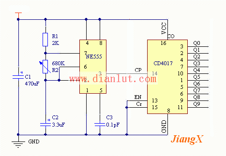
The lantern circuit consists of two integrated blocks: one is the NE555, which produces a binary-variable, frequency-adjustable square wave; the other is the CD4017, which converts the binary to a decimal digital decoder, looping on a decimal basis. This circuit can make 10 multiple light sources work alternately in decimal order. The following are the parts that make up the circuit and how they work. figure 1 Solid-state Capacitors / Motor Starting Capacitors
Solid - state capacitors are all called: solid - state Aluminum Electrolytic Capacitors.It with the ordinary capacitance (that is, the liquid aluminum electrolytic capacitors) the biggest difference is that use different dielectric material, liquid aluminum capacitor dielectric material as the electrolyte, and solid-state capacitor dielectric material is conductive polymer materials.Solid-state capacitors / Motor starting capacitors
Solid-state capacitors / Motor starting capacitors,Solid-State Capacitors,Solid-State Small Size Capacitors,Solid-State Low Impedance Capacitors,Long Life Solid-State Capacitors YANGZHOU POSITIONING TECH CO., LTD. , https://www.cnpositioning.com
The power circuit is an ordinary DC 9V power supply, preferably with a voltage regulator circuit, I will not repeat it for you.
The oscillating circuit is composed of a time base integrated circuit NE555 and C2, C3, R1, R2, etc. (C2 is a delay charging capacitor, C3 is an anti-interference isolation capacitor, R1 and R2 are delay charging resistors, and R2 is a discharging resistor. ). After power-on, the voltage across the capacitor C2 cannot be abrupt, the voltage of the 2 pin is low, the internal flip-flop of the integrated block NE555 is set, and the 3 pin outputs a high level. At the same time, since the power supply charges C2 through the resistors R1 and R2, the voltages of pins 6 and 2 are continuously increased. When the potential rises to 2/3 of VCC, the internal flip-flop of the integrated block NE555 is reset, and the output voltage of the 3-pin is output. Flip to low. At the same time, the discharge tube inside the integrated block NE555 is turned on, that is, the 7th pin communicates with the 1 pin through the internal discharge tube, and the charge stored on the C2 is discharged through the R2 and 7 feet, so that the voltages of the 6th and 2nd feet are continuously decreased, when the potential When reduced to 1/3 of VCC, the internal flip-flop of the integrated block NE555 is set. At the same time, the discharge tube inside the integrated block NE555 is cut off, the 7-pin is suspended, and the power supply is charged to C2 through R1 and R2, so that the voltage of the 6-pin and the 2-pin is continuously increased... Thus, the oscillation is formed repeatedly. The high-level sustain time of the output depends on the charging time constant of the capacitor C2, and the low-level sustaining time of the output depends on the discharge time constant of the capacitor C2. Since R2 ≥ R1, it can be considered that f is charged, and the purpose is to reduce the difference in the time interval in which the lanterns are turned off alternately. If used in other situations, the course adjusts the parameters of R1, R2, and C2 as needed. In summary, the 3 pin is always in a binary state of high level and low level, so the circuit is also called an unsteady circuit.
The decoding circuit consists of a CD4017 integrated block. The manifold has three inputs (14 pins for 2 clock inputs CP and 13 pins for EN and 15 pins for reset terminal Cr). There are 10 output terminals Q0~Q9 (3 feet, 2 feet, 4 feet, 7 feet, 10 feet, 1 foot, 5 feet, 6 feet, 9 feet, 11 feet). There is also a carry-end CO, whose function is: When the reset terminal Cr is added with a high level and a positive pulse, the output terminal Q0 is at a high level, and the remaining 9 output terminals Q0 to Q9 are at a low level. The clock output CP counts the rising edge of the input clock pulse and EN counts the falling edge of the clock pulse. The output states of the 10 outputs of Q0~Q9 correspond to the number of clocks input. If counting from 0, Q1 becomes high when the first clock pulse is input, and Q2 becomes high when the second clock pulse is input... until the 10th clock pulse is input, Q0 becomes Is high. At the same time, the carry terminal C0 outputs a carry pulse as a clock signal for the next stage count. Cr is the reset terminal and is also the clear terminal. When Cr is input to a high level, the circuit is reset, that is, the output terminal Q0 is at a high level, and Q1 to Q9 are at a low level. Repeatedly, as long as the binary signal sent from the 3 pin of the integrated block NE555 does not disappear, the CD4017 will convert the binary signal into the decimal signal and the counting operation will be repeated.
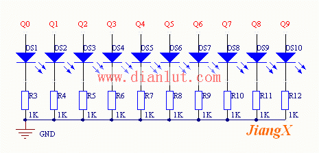
The light source circuit is mainly composed of high-brightness light-emitting diodes and current limiting resistors, as shown in Figure 2:
Figure 2 is a simplified and basic light source circuit. In the following works, the 10 output terminals Q0~Q9 of CD4017 drive multiple LEDs in parallel to control the 10 lights respectively, because the high brightness LEDs With low power consumption, so more than a dozen can be used in parallel with the CD4017. If the power of the light source is too large, you can try to control each light with a thyristor. As for how the light source is arranged, it depends on how you design yourself. Note that after each group of light sources is connected in parallel with multiple LEDs, the value and power of R3-R12 must be changed. 

Figure 2 light source circuit