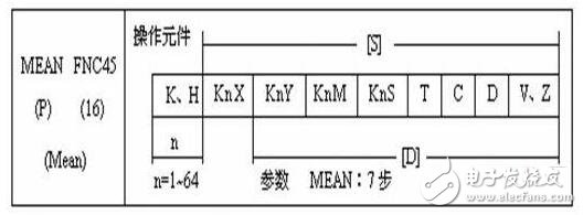
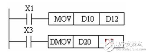
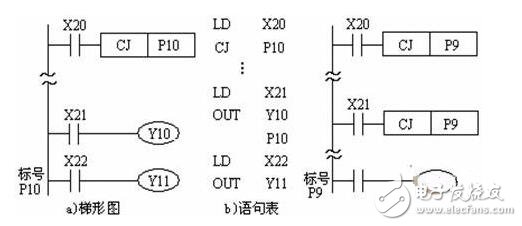
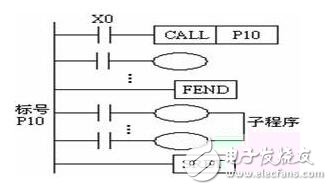
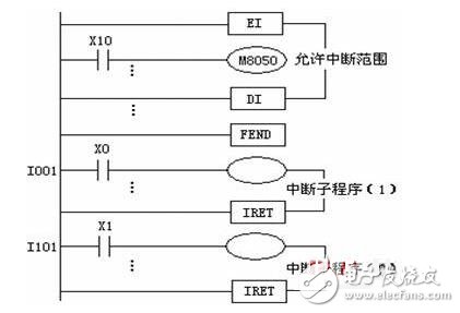
1. General expressions and features of function instructions The expression of the function instruction is shown in the following table: The function commands are organized by function number FNC00~FNC249. Each function instruction has an instruction mnemonic. 2, data length Function instructions can process 16-bit data and 32-bit data. The first instruction in the following figure is to send the data in D10 to D12, which is processing 16-bit data. The second instruction is to send the data in D21 and D20 to D23 and D22, and process 32-bit data. 3, function instruction type The function commands of the FX series PLC are in the form of continuous execution and pulse execution. The program in the left is an example of a continuous execution mode. The above instruction is repeatedly executed every scan cycle when X2 is in the ON state. The program right program is the pulse execution mode, which is valid only when X1 turns from OFF to ON. 4, bit components Bit component: A component that only processes the ON/OFF state is called a bit component. Word component: a component that processes data is called a word component Combination of bit elements: Data processing can be performed by bit elements or word elements, and bit element combinations are represented by Kn plus first element numbers. The four bit elements are grouped into a unit, and n in KnM0 is the number of groups. 5, the index register V, Z The index register is used to modify the component number of the operation object in the transfer and compare instructions. It operates in the same way as a normal data register. The (.) in [D.] indicates that an index register can be added. For 32-bit instructions, V is 16 bits high and Z is 16 bits low. When the index register is used in a 32-bit instruction, only Z is specified, and Z represents V and Z. Second, the program flow control function instruction Conditional jump instruction CJ Subroutine call instruction CALL and return instruction SRET Interrupt return instruction IRET, enable interrupt instruction EI and disable interrupt instruction DI Main program end instruction FEND Watchdog timer refresh command WDT Loop start instruction FOR and loop end instruction NEXT 1, conditional jump instruction CJ The CJ and CJP instructions are used to skip a part of the sequence program to reduce the scan time. Conditional jump instruction CJ application description 2, subroutine call instruction CALL and return instruction SRET The subroutine should be written after the main program, ie the label of the subroutine should be written after the instruction FEND, and the subroutine must end with the SRET instruction. 3. Interrupt return instruction IRET, enable interrupt instruction EI and disable interrupt instruction DI The PLC is generally in an interrupt-free state. The block between the commands EI~DI is the interrupt enable interval, and the interrupt interval is between DI and EI. When the program executes to the allowable interrupt interval and the interrupt request signal appears, the PLC stops executing the main program and executes the corresponding interrupt subroutine. When the interrupt return instruction IRET is encountered, it returns to the breakpoint and continues to execute the main program. 4, the main program end instruction FEND The FEND instruction indicates the end of the main program and the start of the subroutine. When the program reaches the FEND instruction, it performs output processing, input processing, and watchdog timer refresh. When it is finished, it returns to step 0. The FEND instruction is typically used with the CJ-P-FEND, CALL-P-SRET, and I-IRET structures (P for the program pointer and I for the interrupt pointer). The pointers and subroutines, interrupt pointers, and interrupt subroutines of the CALL instruction should be placed after the FEND instruction. The subroutine called by the CALL instruction must end with the subroutine return instruction SRET. The interrupt subroutine must end with the interrupt return instruction IRET. 5, watchdog timer refresh command WDT If the scan time (from step 0 to END or FEND) exceeds 100ms, Mitsubishi PLC will stop running. In this case, the watchdog timer should be refreshed by inserting the WDT instruction into the appropriate program step (scan time not exceeding 100ms). 6, loop start instruction FOR and loop end instruction NEXT The program between FOR~NEXT is executed n times (specified by the operand) and then executed after the NEXT instruction. The number of cycles n ranges from 1 to 32767. If the value of n ranges from -32767 to 0, the number of loops is processed as 1. FOR and NEXT always appear in pairs, and should be FOR before and NEXT after. The FOR~NEXT loop instruction can be nested up to 5 levels. The FOR~NEXT loop body can be jumped out using the CJ instruction. Compabile Models: Guangzhou HangDeng Tech Co. Ltd , https://www.hangdengtech.com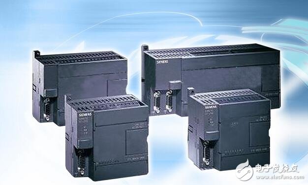

For Samsung:
For Galaxy S6, For Galaxy S6 Edge, For Galaxy S6 Edge+,
For Galaxy S6 Active, For Galaxy S6 Duos, For Galaxy Note Edge,
For Galaxy S7, For Galaxy S7 Edge, For Galaxy Note 5
For Galaxy S8, For Galaxy S8 Plus, For Galaxy Note 8
For Galaxy S9,For Galaxy S9 Plus
For Sony:
For Xperia Z4V, For Xperia Z3V
For Google:
For Nexus 4, For Nexus 5, For Nexus 6, For Nexus 7
For MOTORALA:
For Moto Droid Turbo, For Moto Droid Turbo 2, For Moto Droid 5
For NOKIA:
For Lumia 920, For Lumia 928, For Nokia Lumia 93, For Lumia 950, For Lumia 950 XL, For Lumia 1020, For Nokia Lumia 1050, For Nokia Lumia 822, For Nokia Lumia 735
For HTC:
For HTC ONE MAX T6, For HTC Incredible 4G, For HTC ONE mini 2, For HTC Droid DNA
For LG:
For LG Nexus 4, For LG Nexus 5, For LG G Pro, For LG D1L, For LG LTE2
For Iphone:
For Iphone8/X/XR/XS Max
For Others:
For YotaPhone 2, For Elephone P9000