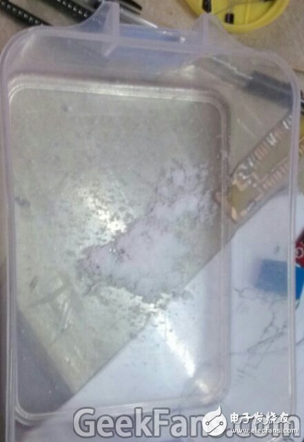
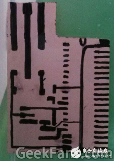
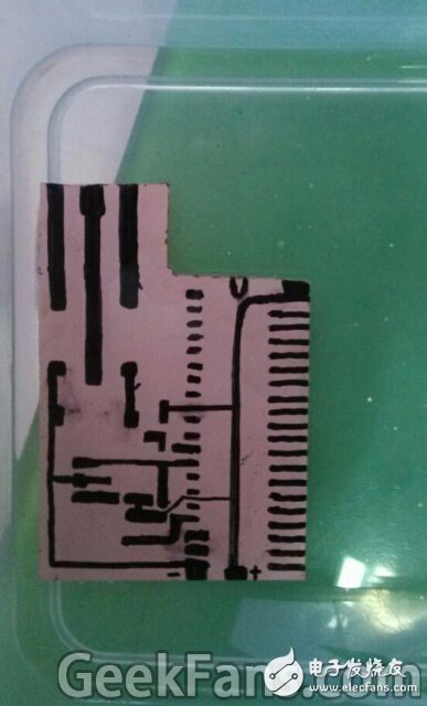
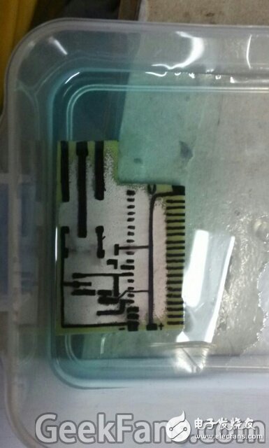
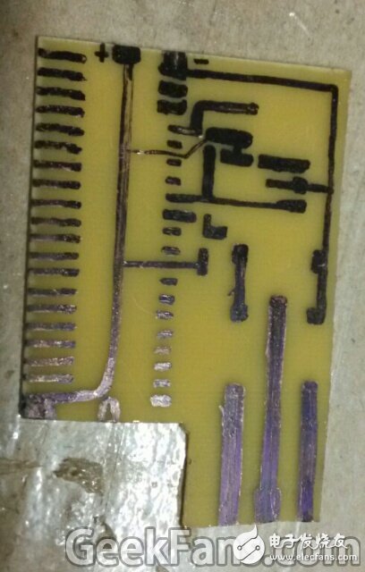
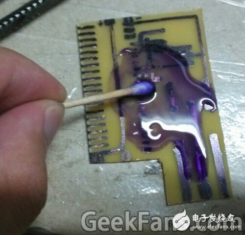
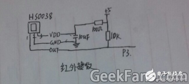
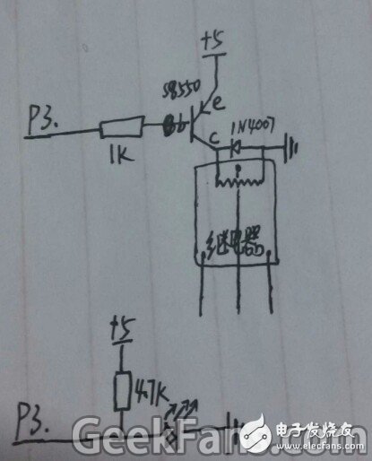
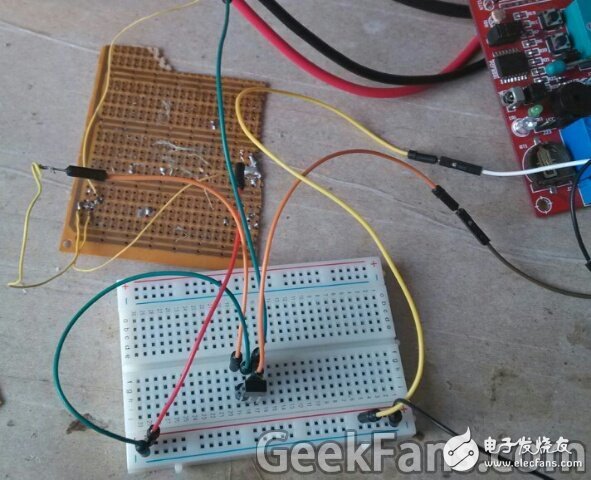
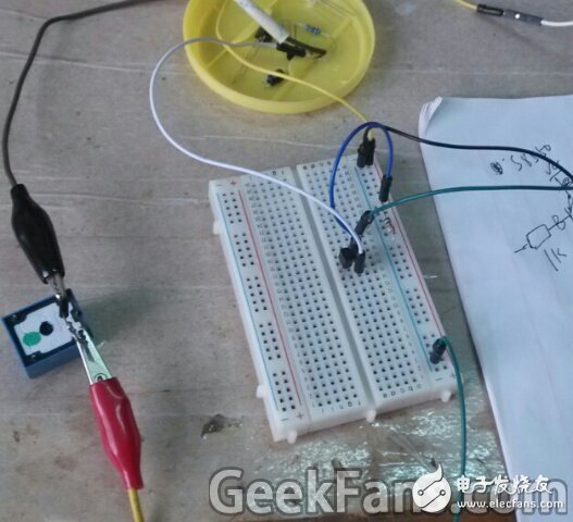
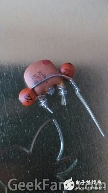
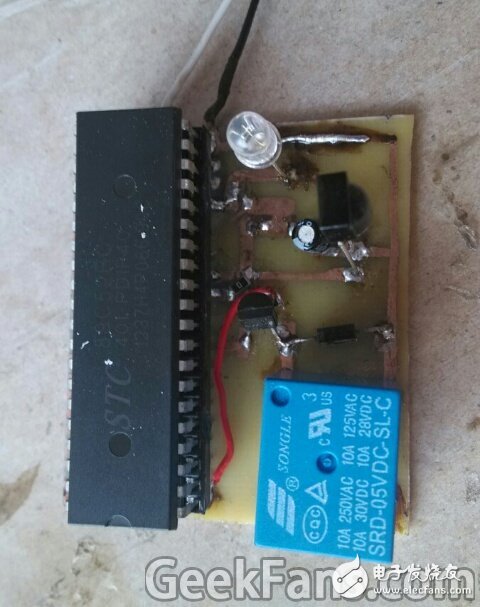
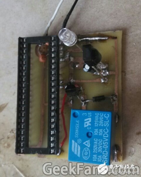
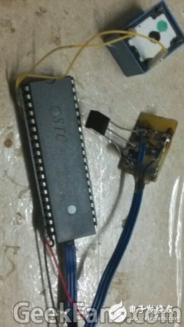
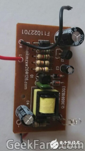
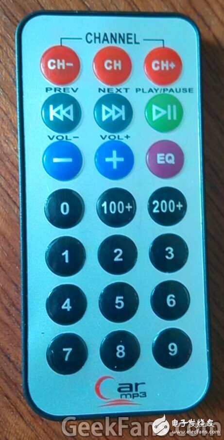
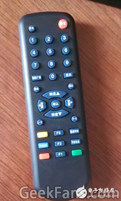
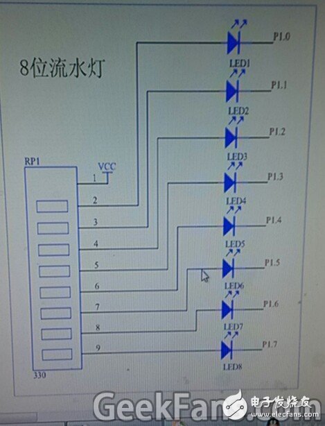
Make an infrared remote control relay as in the title. As for its purpose, I originally made it to remotely control the lights in the room. I installed it in the light switch or next to the light, and the remote control was placed on the side of my bed. Of course it can also be used elsewhere, you can use your imagination. material: 1K 10K 100 ohm 4.7K resistor each One IN4007 diode Two 10~30pf ceramic capacitors 11.0592M crystal oscillator (change to another crystal oscillator, the program has to be changed a bit, I have written in the program, plus or minus 1M should be no problem) One 51 single-chip microcomputer (the specific model you choose, the smaller the better, I only have STC89C52 on hand, which is big and has many pins. It is a bit wasteful to do this, but there is no way) (STC12C2052 seems to be very consistent) One MCU seat One S8550 transistor One 5V relay One light-emitting diode 10uf electrolytic capacitor One HS0038 integrated infrared receiver tube Disused remote control (38K carrier, otherwise HS0038 cannot be identified) As for the use of infrared instead of wireless modules, the biggest reason is the cost, and it also reduces the production threshold and cost to a certain extent. Blue environmentally friendly etchant bought online, add a small amount of water Do not use a printer, draw by yourself. If it is ugly, you can draw with a ruler, whatever you want. Oil-based pen, this kind of pen can definitely be painted on the copper clad laminate. It dries quickly. It saves the trouble of using a computer to draw a PCB and no printer. The point is that it will not be dissolved by water after it dries. Put it in the etchant, after a while, the heating can be faster Corrosion is complete, take it out, dissolve the ink with alcohol, and then rinse with water This is the circuit part, and the P3. is connected to the pins of the single-chip microcomputer (I didn’t specifically write P3 in the picture), mine is P3.2 connected to infrared detection, P3.7 is connected to light-emitting LED, and P3.6 is connected to relay. When you do it, you decide which pin to use. Finally, you only need to modify the program. I have a comment in it. The raised side of HS0038 faces itself, from left to right are output, GND, VCC. The relay itself has marked pins. The LED is to see the status of the relay intuitively, the high and low levels are the same as the relay These two are my test circuit, practice test, to ensure that the circuit is available The crystal oscillator is disassembled on a certain circuit board, and the capacitor is directly soldered on top This is done by my own soldering. It is a bit different from the circuit board I made before. Temporary changes are possible. This is one of the versions, which is a bit big and can’t fit in the socket. . . I made another version, this time it’s modularized, and the single-chip microcomputer is better. So I asked you to choose the single-chip microcomputer at the beginning. I only have this kind of microcomputer at hand. I can only do this. There are many useless IO ports. ,wasted. Electronic components can be concealed under the single-chip base, the smaller the size, the better. The circuit board on the old mobile phone charger, which outputs 5V, is used to supply power to the single-chip microcomputer Since the switches at home are quite new, I dare not continue with the rest, because I have to dig a hole to expose the infrared receiver. So I can only install it next to the lamp. I won’t demonstrate it here. It’s very simple. I believe everyone’s ability. Don’t forget to insulate the switch inside. Wrap it with black tape. 220v into the MCU, no consequences. Dare to imagine. One relay can only control one channel, and the fire wire and the zero wire can be selected by themselves. I put the program in the network disk, open it to see where there are comments, it is the hardware changes that need to be modified, there is a written in it how to change There are two remote controls in my house, both of which can be used, but their user codes are different. I did not perform user code recognition in the program. As long as the key code is enough, I have already figured out how to get the key code. The program is below. Port P1 is the key code. The high level is 1, the low level is 0, P1.7 is the highest bit, and the lowest bit of p1.0. Take down the eight bits in turn. These eight bits are binary and converted to decimal. It's the key code You can make a water lamp, the circuit is as follows If it is not bright here, it means 1, and bright means 0. The 330 ohm resistor is used for current limiting (you can also directly use a multimeter to test, or just connect one LED to test one by one, don’t forget to connect the current limiting resistor), infrared input Still p3.2 If it is not recognized, hold a few more buttons against the infrared. No response, either the circuit is faulty, or the remote control is not 38K carrier So far you're done.
CKB currency is the brand new upgrade of this small mining coin in the sales market in 2020. The first mining machine to release this currency is developed by Toddminer, a team of ToddMiner. They became interested in the new Nervos project in early 2019, and immediately invested their scientific research energy when the Nervos team released CKB's Eaglesong optimization algorithm. After 2 years, ibelink finally developed a 32T KDA machine emperor, and the price is affordable compared with KD6, cost-effective and stable pressure tube over KD6 head, and there are two ways to convert freely, emerald green way calculation rate is only 22T, but the function loss is reduced to 1850w, customers can choose the different way according to their own situation. As a new star in the mining circle, iBelink company's new implementation of BM-K1,BM-N1 is obligatory. BM-K1 mainly mines KDA coins, with a calculation rate of 5300G, a functional loss of only 800W, and a daily profit of 300+. And BM-N1 went up with 6.6T calculation rate to kill the small ant K5, ranked first.
Asic Miner IbeLink:iBeLink BM-K1 Max,iBeLink BM-K1,iBeLink BM-K1+
asic miner ibelink,ibelink miner,ibelink bm k1 max,bm k1 miner,ibelink kda miner Shenzhen YLHM Technology Co., Ltd. , https://www.asicminer-ylhm.com