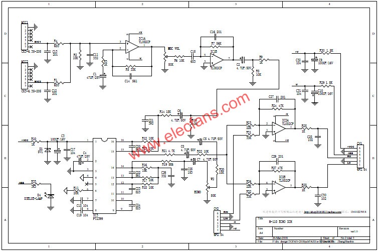
KALAOKE circuit principle 1) The microphone input is introduced by two microphone seven-pin sockets. When the microphone is not inserted, the microphone output signal is shorted to GND. Only when the microphone is plugged in, the microphone output signal will be disconnected from GND and effectively output to the post-stage power amplifier. The circuit diagram is not drawn. The 7-pin microphone has a set of switches. The microphone is not inserted. The output is short-circuited to ground to achieve the effect of noise suppression. The microphone will automatically open shortly and the audio path is unobstructed. Let's find a 7-legged study. 2) After the microphone input signal passes through the positive-phase amplifier tube of the IC1A dual op amp side amplifier, the 50K single potentiometer (2W1) realizes the microphone MIC VOL attenuation adjustment. The microphone signal after the volume adjustment passes through the first-stage common-emitter amplifier circuit In the same way, the other side of IC1B dual op amp achieves reverse phase amplification. The microphone signal finally enters RSM2399 for reverberation (ECHO) processing. Adjusting the resistance value of the ground resistance at the bottom and foot of 2399 can change the reverberation delay time. Generally speaking, the standard is to hear 7 echoes that fade in succession. 3) RSM2399 can handle the delay effect of audio signals. For the connection of peripheral components, please refer to DATASHEET of PT2399. KALOKE circuit maintenance 1) MIC microphone circuit failure: the microphone has no sound and no output. A) Check the MIC circuit power supply maintenance steps. First confirm that the power supply of the RSM2399 is normal. The voltage of the PIN1 pin of the normal power supply RSM2399 is 4.7V to 5V, and 5V when there is no signal input. It must also confirm that the power supply of the microphone IC1 dual op amp is normal. B) Check the input of MIC signal in the MIC signal path (insert the microphone for sound test and test at the same time), and use an oscilloscope to observe whether C15 has a coupled signal output. Note: The microphone is plugged in, and the output signal is still short-circuited to the ground. The microphone socket is defective and must be replaced. In the normal state, if neither microphone plug is inserted into the microphone, the signal is shorted to ground, and if any one is inserted, the signal will no longer be shorted to ground. 2) MIC circuit failure: adjust the MIC VOL or ECHO to have a noise overhaul step. The focus should be on the quality of the MIC VOL / ECHO potentiometer, check whether the reed contact inside the potentiometer, you can use special cleaning fluid or industrial alcohol to clean the inside of the potentiometer , If conditions permit, replace the bad potentiometer directly. 3) MIC circuit failure: the focus of the MIC sound distortion maintenance steps should be placed on two op amps (IC2 op amp mixes the MIC signal with other audio signals as an adder to make the vocal and music superimposed KALAOKE) and RSM2399 itself quality or Peripheral component quality. Focus on checking whether their power supply is normal, replace components if necessary, and use the "substitution method" to narrow down the problem area until the problem is found and eliminated. 4 layer PCB Board Storm Circuit Technology Ltd , https://www.stormpcb.com
If there is no signal output from C15 indicating that the fault is in the MIC dual op amp IC1 amplifier circuit, it is necessary to focus on detecting IC1 amplification, whether the power supply is abnormal or the coupled electrolytic open circuit, the volume potentiometer is soldered, and the signal short circuit and other defects can be eliminated.
If the C15 has a signal output indicating that the RSM2399 input signal is OK, but the RSM2399 has no output, first check whether the 2C11 coupled signal is shorted to ground due to a poor microphone socket. Otherwise, check the RSM2399 peripheral circuit and RSM2399 quality. 