Ultrasonic humidifier (ultrasonic atomizer) circuit and production

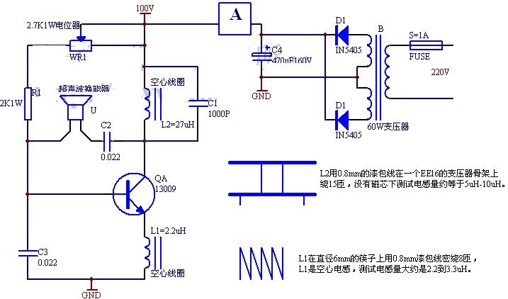
See the following circuit diagram: a high-power high-frequency oscillator composed of QA, L2, C1, L1, C3, C2, R1, U and WR1, using a capacitive three-point oscillation circuit, the oscillation frequency of the circuit is the ultrasonic piezoelectric transducer U The natural frequency is 1.013MHz. The resonance circuit composed of L2 and C1 does not determine the oscillator frequency here, but determines the oscillation amplitude. Its resonance frequency is lower than the oscillation frequency of the circuit. The resonance frequency of L1 and C3 is greater than the oscillation frequency of the circuit. The use of two resonance circuits is In order to synthesize the oscillation frequency of the circuit, the oscillator is guaranteed to work stably under high power.
Ultrasonic humidifier (ultrasonic atomizer) is a method of generating high-frequency vibration by ultrasonic energy conversion to atomize the water surface. During the atomization process, the water mist is continuously evaporated to the surroundings to maintain a certain humidity in the air.
See the following circuit diagram: a high-power high-frequency oscillator composed of QA, L2, C1, L1, C3, C2, R1, U and WR1, using a capacitive three-point oscillation circuit, the oscillation frequency of the circuit is the ultrasonic piezoelectric transducer U The natural frequency is 1.013MHz. The resonance circuit composed of L2 and C1 does not determine the oscillator frequency here, but determines the oscillation amplitude. Its resonance frequency is lower than the oscillation frequency of the circuit. The resonance frequency of L1 and C3 is greater than the oscillation frequency of the circuit. The use of two resonance circuits is In order to synthesize the oscillation frequency of the circuit, the oscillator is guaranteed to work stably under high power.
Transistor adopts 13009 plus heat sink, R1 and WR1 are bias resistors, adjust WR1 to make the oscillator output moderate, and make sure that the circuit has started to oscillate. Here, A is an ammeter, and the entire circuit current is determined to be about 0.4A. Too.
Fix the atomizing sprinkler head on the bottom of the basin, the water depth is preferably 6-10cm. Adjust the potentiometer WR1, first turn the potentiometer to the maximum resistance. Turn on the power supply, slowly reduce the resistance value of WR1, observe the ammeter and the water spray, until the water mist is the highest and the amount of mist is the largest, and the current is the smallest, you can replace the potentiometer WR1 with the same resistance value.
Then start the second step adjustment! Knock the short-wave magnet into magnetic blocks of different sizes and put them into the skeleton of L2. After repeatedly selecting the magnetic blocks of different sizes, carefully observe the new situation of ammeter and water spray! At this time, the water mist should be higher than the front and the fog volume is larger, and the current is smaller than the front, and the temperature of the triode is lower. Finally, fix the magnetic block in the L2 skeleton. If there is a new debugging method, we will update the technical information of the electronic production network here.
Component selection and production C1, C2, C3 high-frequency ceramic dielectric capacitor voltage 630V. The transistor requires 60W of power and a switch with a backpressure greater than 300V.
Dongguan Guancheng Precision Plastic Manufacturing Co., Ltd. , https://www.dpowerchargers.com