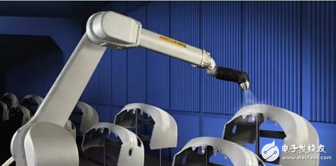
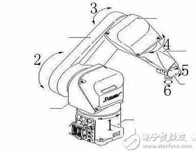
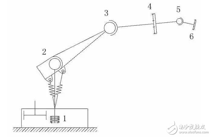
The design of industrial robots is the same as most mechanical design processes; first of all, why should we design robots? What functions can the robot achieve? How big is the activity space (effective working range)? After understanding the basic requirements, the next work is done. The first is to determine the type of robot according to the basic requirements, whether it is a lifting (lifting) robot arm, a three-axis coordinate robot, or a six-axis robot. The type of robot is selected to determine the control method, and there is a guiding direction for design in a limited space. The next thing to do is to determine the design task. This is a relatively complicated process. The first step in implementing this complex process is to clearly define the design requirements. The second step is to make a mechanical transmission sketch according to the design requirements, analyze the sketch, and formulate the action flow chart. ), initially determine the transmission power, control process and method; the third step is to clearly define the design content, design steps, design points, design calculations, sketch drawing, materials, processing technology, control procedures, circuit diagram drawing; the fourth step is comprehensive review Confirm the production in all aspects. Below I will clarify this design process with a six-axis industrial robot as the design object: Before I introduce the robot design, let me talk about the application field of the robot. The application fields of robots can be said to be very extensive. There are many examples in automated production lines, such as weight robots, packaging robots, and transfer robots. There are also many examples in welding, such as welding robots on automobile production lines; The development of robots is now very rapid, and the application of robots is also extended in various industries of civil enterprises. The demand for robot design talent is also growing. Six-axis robots have different application models and different design forms. There are also many companies that produce robots in the world, and each has its own structure. The most widely used robots in China such as ABB, Panasonic, FANUK, and Motoman. Since the application of robots is so extensive, there are no well-known production companies in China. As a Chinese mechanical engineering technician, it is a question worth considering! There are too few discussions about robotics? Practitioners still can't be a group? Although the machine's theories can be seen in many places, there is no such thing as universal popularity. Now that I want to talk about design, then I will start from scratch. Try to talk about the general and concise, and if you are wrong, please correct me! The six-axis robot is a multi-joint, multi-degree-of-freedom robot with many movements and flexible changes. It is an industrial robot with high flexibility and the most extensive application. So how do you design it from scratch? How to determine the scope of work? How to arrange the action? How to control the posture? What are the requirements for the joints in each part? and many more. . . . . . Let us go slowly with lots of questions! First of all, we set: the robot is a six-axis multi-degree-of-freedom robot, the standard claw welding torch for holding the oxygen gas protection welding; the welding parts with different requirements such as spot welding and continuous welding are completed, and the process requirements and the process route change rapidly. on-line. Maximum elongation: 1700mm; rotation 270 degrees; base and horizon level fixed; full motor drive. Well, with such basic requirements, we can think about the initial plan. The first is the all-motor drive, then we should not consider the various structures of hydraulic and pneumatic pressure when considering the solution, that is, the transmission mechanism can only use mechanical mechanisms such as rack and pinion and linkage mechanism. Robots are used for welding, so let's examine the various welding techniques and methods under artificial behavior. There is a very complicated thing in it, that is, the welding process; that is, if the welding technique is not fixed, we will distinguish it. In the common welding, there are single point spot welding, continuous break point spot welding, continuous flat seam welding, Fillet welding, vertical seam welding, overhead welding, circumferential seam welding, etc. . . . . . Knowing all kinds of welding methods, I understand that to achieve these complex actions, we must have a set of feasible control methods; before the machine is completely designed, we can not think too much control plan, there is a rough The contour concept will be fine. After the mechanical structure is completed, the driving power of each aspect is determined and detailed procedures are performed. The welding torch is a commonly used standard welding torch, which means that the welding torch can be replaced at any time, which requires us to quickly lock and loosen the clamping part of the welding torch. When the welding torch is subjected to various welding posture adjustments during the welding process, the mechanical wrist is flexible and can be adjusted in various azimuth angles. With the above basic requirements and setting conditions, the program reasoning has also been organized. Next, we will clarify the design requirements, and the design direction will not be too far off. Design task Design requirements: The robot is suitable for the welding field and can complete various welding actions. For the robot to adapt to various welding processes, the online adjustment process is fast, flexible control program is adopted when programming the control program, adaptive online and offline teaching procedures; weld seam , welding pool, bead imaging tracking, automatically adjust the parameters of the welder. The robot is fully servo driven and the ground is fixedly mounted. Six-axis control, flexible movement of each joint, design the range of motion of each axis according to the process description table, try to make the mechanism compact and the overall appearance is beautiful. design content Mechanical design: design the mechanical mechanism of each joint according to design requirements and process description, determine the material and processing technology of each component; make calculation book, check mechanical strength, drive power and give maximum weight (lifting) weight, inertia of each motion path Calculation, control calculation of pose. Check the service life of all key components of the robot. Create robot maintenance instructions in conjunction with control programs and circuits. Program control design: design the control flow according to the design requirements and the final process route of the mechanical engineer; combine the mechanical structure and drive, signal feedback mode, design the robot motion program; the program should have adaptive function, automatic fixed point tracking, welder current, The voltage is monitored in real time and automatically adjusted; the imaging monitoring and discrimination technology for the weld bead and the weld pool. Design circuit diagram With such a document, we have designed it; then the first thing we have to do is to draw a robotic motion diagram, plan the robot's motion trajectory, and then we can design the mechanical mechanism and consider the program. The road map is up. Let's start with a sketch to study the movement rules. Robot motion diagram: When we sketch the mechanical motion, the general case is to analyze the sketch first; although the sketch does not fully reflect the composition of the mechanical structure, it shows the overall outline of the object to be designed.
Glass tube fuses are made by glass shell, some metal wires and two brass caps. Fuse is small safety part in an electrical device or piece of machinery that causes it to stop working if the electric current is too high, and so prevents fires or other dangers. Fuse in the abnormal current increases to a certain height and heat, its own fuse to cut off the current, to protect the safe operation of the circuit fuse protection power equipment with current overheating damage, avoid electronic equipment serious damage caused by internal fault. When a circuit breaks down or is abnormal, the current increases with the current and the increased current may damage some important components in the circuit, and it may also burn the circuit and even cause a fire. If correctly placed in the circuit fuse, the fuse will be abnormal current increases to a certain height and heat, its own fuse to cut off the current, so as to protect the safe operation of the circuit.
Auto Glass Tube Fuses Auto Glass Tube Fuses,Max Fuse,High Quality Blade Fuse,Fuse Block SHINING BLICK ENTERPRISES CO., LTD. (Heshan Jianhao Lighting Industrial Co., Ltd.) , https://www.sunclubtw.com

