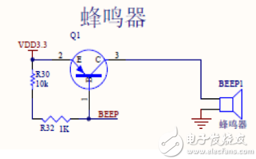
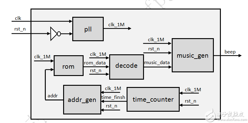
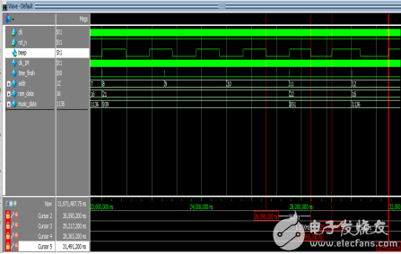
The buzzer is a kind of electronic buzzer with integrated structure. It uses DC voltage to supply power. It is widely used in computers, printers, copiers, alarms, electronic toys, automotive electronic equipment, telephones, timers and other electronic products as sound devices. . In a general design, the buzzer can be used to detect whether some buttons are pressed, or whether some functions are normal, etc. Of course, if it is romantic enough, the buzzer can also be used to play music. This design uses a passive buzzer, which can also be called a buzzer. The principle circuit diagram is shown below. It has no internal driving circuit. The ideal signal for passive buzzer is a square wave. If it is supplied with direct current, the buzzer will not respond because the magnetic circuit is constant and the molybdenum sheet cannot vibrate and pronounce. According to the circuit diagram, due to the insufficient drive capability of the FPGA, a triode is added to drive the passive buzzer. When driving, you only need to send a square wave of a certain frequency to the buzzer to make the buzzer sound. So what frequency should be sent? For details, please refer to the following table (syllable frequency table): The two basic data required for continuous performance of a music piece are: the frequency value (pitch) of each note composing the music piece and the duration of each note (pitch length). Therefore, as long as the frequency and duration of the excitation signal output from the FPGA to the buzzer are controlled, the buzzer can emit continuous music sounds. In this design, since the crystal oscillator to the core development board is 50MHz, we need a frequency divider module (PLL) to generate a lower reference frequency (1MHz). It also needs a space to store the music score. Since the music score is fixed and does not need to be changed, we choose the ROM IP core for storage. The reference frequency of 1MHz can be divided to obtain signals of all different frequencies. The maximum division ratio is 1_000_000/262/2. Since it is music, it needs a beat, generally 4 beats, that is, the sound length is 0.25s, so it is necessary to design a module to control every 0.25s, the ROM address is increased by 1. If you need to send a bass 1 and maintain it for 1 second, you only need to write the corresponding information of the bass 1 in the four consecutive addresses of the ROM. For the convenience of storing data in ROM in the design, the data format here is 8'hAB, where A is temporarily three values ​​1, 2, and 4, respectively representing bass, midrange, and treble. B temporarily has seven values ​​of 1, 2, 3, 4, 5, 6, and 7. For example, if you want to generate a bass 1, you only need to store 8'h11 in ROM, if you want to generate a treble 7, you only need to store 8'h47 in ROM, and so on. At this time, a decoding module is needed to restore the data in the ROM to the data required by the music generator. Design architecture diagram: According to the above analysis, the following architecture diagram is obtained: The design includes 6 modules. The PLL module reduces the 50MHz clock signal to 1MHz, the rom module stores music data, and time_counter is a counting module that generates beats. Every 0.25s, the output TIme_finsh becomes a high level of a cycle. And send it to addr_gen module, generate addr, let rom output the data of the next address. The data rom_data output by the rom is input to the decode decoding module, and the decoded data music_data is input to the music_gen module, through the counter, if the counter is less than the value of music_data, the beep remains unchanged, otherwise, the beep is inverted and the counter is cleared to 1, thus Generate a specific square wave frequency. Design code: The TIme_counter module code is as follows: 0 module TIme_counter(clk, rst_n, TIme_finsh); 1 2 input clk, rst_n; //input 1Mhz clock signal, reset signal 3 output time_finsh; //Output time count flag bit (change to high level once every 0.25s) 4 5 reg [17:0]count; //counter count 6 7 always@(posedge clkor negedge rst_n) 8 begin 9 if(!rst_n) 10 count 11 else if(time_finsh) 12 count 13 else 14 count 15 end 16 /*****Every 0.25s, time_finsh is pulled up, indicating that it has reached 0.25s*****/ 17 assign time_finsh = (count== 18'd249_999)? 1'd1: 1'd0; 18 /*****Used for simulation, because the real 0.25 will be very long for simulation*****/ 19 //assign time_finsh = (count == 22'd25_00)? 1'd1: 1'd0; 20 21 endmodule The addr_gen module code is as follows: 0 module addr_gen(clk, rst_n, addr, time_finsh); 1 2 input clk, rst_n; //input 1Mhz clock signal, reset signal 3 input time_finsh; //Input time count flag bit (change high level once every 0.25s) 4 output reg [6:0]addr; //Address signal output to ROM 5 6 always@(posedge clkor negedge rst_n) 7 begin 8 if(!rst_n) 9 addr 10 else if(time_finsh) //Add 1 to the address signal output to ROM (add 1 every 0.25s) 11 addr 12 else 13 addr 14 end 15 16 endmodule The decode module code is as follows: 0 module decode(clk, rst_n, rom_data, music_data); 1 2 input clk, rst_n; //input 1Mhz clock signal, reset signal 3 input [7:0]rom_data; //Input ROM data 4 output reg [10:0]music_data; //output ROM decoded data 5 6 always@(posedge clkor negedge rst_n) 7 begin 8 if(!rst_n) 9 music_data 10 else 11 case (rom_data) 12 8'h11: music_data 13 8'h12: music_data 14 8'h13: music_data 15 8'h14: music_data 16 8'h15: music_data 17 8'h16: music_data 18 8'h17: music_data 19 20 8'h21: music_data 21 8'h22: music_data 22 8'h23: music_data 23 8'h24: music_data 24 8'h25: music_data 25 8'h26: music_data 26 8'h27: music_data 27 28 8'h41: music_data 29 8'h42: music_data 30 8'h43: music_data 31 8'h44: music_data 32 8'h45: music_data 33 8'h46: music_data 34 8'h47: music_data 35 36 8'h00: music_data 37 endcase 38 end 39 40 endmodule The music_gen module code is as follows: 0 module music_gen (clk, rst_n, music_data, beep); 1 2 input clk, rst_n; //input 1Mhz clock signal, reset signal 3 input [10:0]music_data; //input music frequency control word 4 output reg beep; //output square wave 5 6 reg [10:0]data, count; //Register music control word data, counter count 7 8 always@(posedge clkor negedge rst_n) 9 begin 10 if(!rst_n) 11 data 12 else 13 data 14 end 15 16 always@(posedge clkor negedge rst_n) 17 begin 18 if(!rst_n) 19 begin 20 count 21 beep 22 end 23 else if(data== 11'd0) //When data==11'd0, (stop the beat) 24 begin 25 count 26 beep 27 end 28 else if(count 29 count 30 else 31 begin 32 count 33 beep 34 end 35 end 36 37 endmodule The beep top-level module code is as follows: 0 module beep(clk, rst_n, beep); 1 2 input clk, rst_n; //input 50Mhz clock signal, reset signal 3 output beep; //output square wave 4 5 wire clk_1M, time_finsh; //1Mhz clock signal line, 0.25s time counting flag 6 wire [6:0]addr; //rom address wire 7 wire [7:0]rom_data; //rom data line 8 wire [10:0]music_data; //rom data decoding data line 9 10 /*****PLL module*****/ 11 my_pll my_pll_inst( 12 .areset(~rst_n), 13 .inclk0(clk), 14 .c0(clk_1M) 15 ); 16 17 /*****0.25s time counter module*****/ 18 time_counter time_counter_inst( 19 .clk(clk_1M), 20 .rst_n(rst_n), 21 .time_finsh(time_finsh) twenty two ); twenty three 24 /*****ROM address generator*****/ 25 addr_gen addr_gen_inst( 26 .clk(clk_1M), 27 .rst_n(rst_n), 28 .addr(addr), 29 .time_finsh(time_finsh) 30 ); 31 32 /*****ROM module*****/ 33 my_rom my_rom_inst( 34 .address(addr), 35 .clock(clk_1M), 36 .q(rom_data) 37 ); 38 39 /*****Decoding module*****/ 40 decode decode_inst( 41 .clk(clk_1M), 42 .rst_n(rst_n), 43 .rom_data(rom_data), 44 .music_data(music_data) 45 ); 46 47 /*****Music generator module*****/ 48 music_gen music_gen_inst( 49 .clk(clk_1M), 50 .rst_n(rst_n), 51 .music_data(music_data), 52 .beep(beep) 53 ); 54 55 endmodule The beep_tp top-level test module code is as follows: 0 `timescale 1ns/1ps 1 2 module beep_tb; 3 4 reg clk, rst_n; 5 wire beep; 6 7 initial begin 8 clk = 1; 9 rst_n = 0; 10 #200.1 rst_n=1; 11 12 //#100000000 $stop; 13 end 14 15 beep beep_dut( 16 .clk(clk), 17 .rst_n(rst_n), 18 .beep(beep) 19 ); 20 21 always #10 clk = ~clk; twenty two 23 endmodule Simulation diagram: The simulation results are as follows: It can be seen from the simulation diagram: when the rom output rom_data is 8'h16, it represents the output bass 6, the decoded result music_data is 1136, and the output beep frequency is 440Hz, which is consistent with the actual bass 6 syllable frequency table value; when the rom outputs rom_data When it is 8'h22, it means that the midrange 2 is output. The decoded result music_data is 851, and the output beep frequency is 563Hz, which is 24Hz different from the actual midrange 2 syllable frequency table. There is a certain error, but it does not affect the music. Play. If you want to improve the accuracy of the beep frequency and reduce the error, you can increase the reference frequency of 1MHz. Product categories of E-cigarette Accessories, we are specialized manufacturers from China, Smoking Accessories, Smoking Accessories suppliers/factory, wholesale high-quality products of Smoking Accessories R & D and manufacturing, we have the perfect after-sales service and technical support. Look forward to your cooperation! smoking accessories,vape accessories box,disposable vape accessories,disposable vape atomizer,e cigarette parts accessories Ningbo Autrends International Trade Co.,Ltd. , https://www.supermosvape.com


