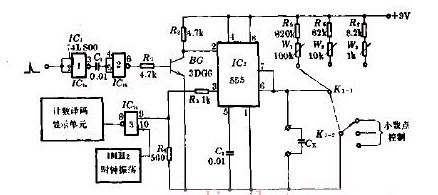
As shown in the figure, it is a digital capacitance measuring circuit that uses digital counting to display the capacitance, and the accuracy can be greatly improved. Here, 555 is used as the counting gate control circuit with an accuracy of 0.5%. K1-1 and K1-2 are range selection switches for synchronous operation. Here, there are 3 speed ranges (10μF, 1Fμ, 0.1μF), which can measure below 10μF. capacitance. The working process is as follows: the start pulse is shaped by the gate 1 and the gate 2, and then inverted by the 3DG6 to become a negative start trigger pulse to trigger the one-shot circuit formed by the 555. The 555 outputs a timing gate pulse that is proportional to the capacitor Cx under test. During this gate pulse, a 1 MHz clock pulse is sent through gate 3 to the count decode display unit. As a result, the count size displayed by the display unit is proportional to Cx, which indicates the size of the Cx capacity. Jinan Guohua Green Power Equipment Co.,Ltd. , https://www.guohuagenerator.com