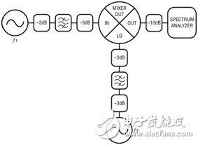
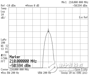
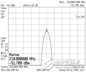
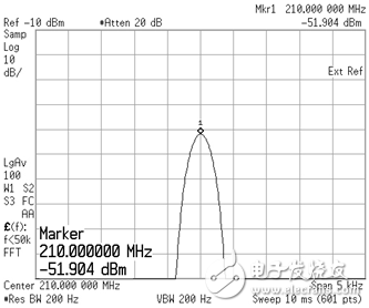
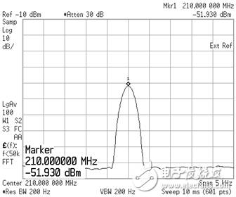
Measuring mixer spurs is not a trivial matter. It is often possible to blindly believe that a "measured" signal comes from the relevant mixer, but in reality it is an artifact of some improper test setup. Fortunately, there are ways to alleviate these test problems and ensure that the observed measurement signals are only from the mixer. Figure 1 shows the correct test setup for measuring the spur component of the mixer. Bandpass filters and attenuators are critical to minimizing the impact of test setup on spurious pulses measured on the spectrum analyzer. Figure 1: Correct test setup for measuring mixer spurious pulses When overdriven, the spectrum analyzer produces significant internal distortion components. When excessive power is applied, the internal receiver link enters a compressed state, causing all nonlinear spur components to grow at an acceleration rate (relative to the main input signal), artificially increasing the measured value of the spurious power. . Spectrum analyzers are typically designed to operate optimally with a power level of approximately -30dBm to -40dBm at their inputs. To meet this power level, internal attenuation, external attenuation, or a combination of the two should be used to limit the power supplied to the instrument. One test to check if the spurious measurements are correct is to increase the internal attenuation settings of the spectrum analyzer and note any changes in the power level of the stray pulses. If the amplitude of the spurious pulse is greater than about 0.5 dB, the spectrum analyzer is likely to be overdriven and the resulting spurious level reading is higher than the actual value. A good starting point for input attenuation is approximately 20dB to 30dB total, internal and/or external. Figures 2 through 5 show the continuous wave (CW) tones measured while increasing the input attenuation of the spectrum analyzer. As the attenuation level increases, the measured power level drops, indicating that the instrument was previously overdriven. Figure 2: 0dB of the 0dB spectrum analyzer input attenuation, the third harmonic of the CW 70MHz tone Figure 3: A 10dB mCm 70MHz tone third harmonic of the 10dB spectrum analyzer input attenuation Figure 4: A third harmonic of a 0dBmCW 70MHz tone at 20dB spectrum analyzer input attenuation Figure 5: 30dB spectrum analyzer input attenuation with a 0dBm CW 70MHz tone third harmonic After seeing that the spectrum analyzer has been driven to produce incorrect spurious measurements, you may decide to simply drive the instrument at a low power level to completely avoid the above problem. If 30dB of attenuation is appropriate, then 100dB of attenuation must be better. Be aware that the spectrum analyzer normalizes the signal as the internal attenuator changes. Unfortunately, this is not feasible if you want to see the spurious pulses of interest. For each dB of input attenuation used (internal or external attenuation, the situation is the same), the noise floor of the instrument rises by 1 dB, which reduces the dynamic range of the instrument, which may hide some of the spurs you are trying to measure. pulse. Note that the noise floor is high and therefore is evident in Figure 5 (compared to Figures 2~4), although the scales are identical. Moreover, the power variation of the higher order spurious component is not linear with the desired output signal. Instead, they vary the magnitude of the power as a multiple of the magnitude of the input power change. The secondary component (2*IN x 1*LO, 2*IN x 2*LO, 2*IN x 3*LO, etc.) will change 2dB/dB, three components (3*IN x 1*LO, 3* IN x 2*LO, 3*IN x 3*LO ... etc.) will change 3dB/dB, and so on. For example, if the input signal power is reduced by 2dB, the spurious level at 5*IN x 2*LO will be reduced by 10dB, while the spurious level at 2*IN x 1*LO will be reduced by 4dB. Therefore, placing a low signal power level into the spectrum analyzer is nothing more than forcing all the low-power spurious pulses you are trying to measure into the noise floor of the instrument. Another common source of false spurious measurements is the lack of input signal filtering. For accurate measurement of spurious levels, it is crucial to use a filter for the input signal to attenuate any signal generator harmonic components. Even laboratory-quality signal generators will only have harmonic suppression levels from -25dBc to -50dBc. Some spurious levels at the output of the Linear Technology mixer will be less than -70dBc, so using a signal generator without a filter is not good enough. For this purpose, filters with a harmonic suppression level of at least 30dB to 50dB should be used. Figure 6 shows the output spectrum of a 100MHz CW tone generated by the Keysight E8257C signal generator. Note the power level of the harmonics of the fundamental signal. These harmonic relative levels should be consistent across a variety of different main tone power levels. Figure 6: A harmonic spurious pulse of a 100MHz CW tone generated by the Keysight E8257C signal generator If you suspect that the input signal may cause the spurious pulse to be higher than expected, it is best to check the operation of the spurious pulse relative to the input signal level. If the spurious pulse is a higher harmonic and does not respond to changes in the signal level with a suitable slope (2dB/dB, 3dB/dB ..., etc.), then the most likely case is the input signal. The source is not clean enough. As shown, measuring the spurious component of the mixer is not always straightforward, but better results can be easily obtained with some small adjustments to the test setup. Setting the input attenuator and applying the correct filtering method for the source will provide a much more accurate and repeatable measurement. Water Proof Axial Fan ,Compact Axial Fan,Axial Air Fan,Co Axial Fan Hangzhou Jinjiu Electric Appliance Co Ltd. , https://www.jinjiufanmotor.com
During mixing, the mixer produces more than just the desired signal at its output. Other unwanted signals at integer multiples of the input and LO frequencies also appear on all ports of the mixer. These spurious signals are then mixed with each other and exit the mixer's output port and enter the rest of the signal chain. Such undesired output signals are referred to as "spur pulses." If the power of these spurious pulses is high enough, it can cause many problems in the RF design, such as contamination of adjacent channels in the transmitter, loss of sensitivity in the receiver, or distortion of the desired signal itself. There are several ways to handle signals of such problems, depending on the requirements of the system. While careful frequency planning and filtering can help to drastically reduce the number of stray pulses, they always have. Therefore, it is important that the system designer must accurately measure the spurious levels at the mixer output to determine how best to deal with them. 