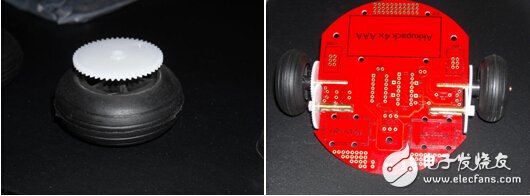
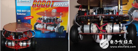
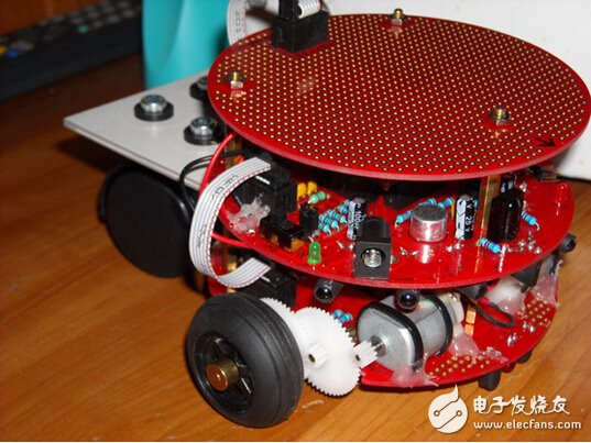
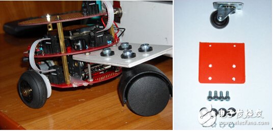
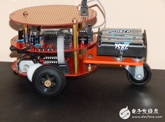
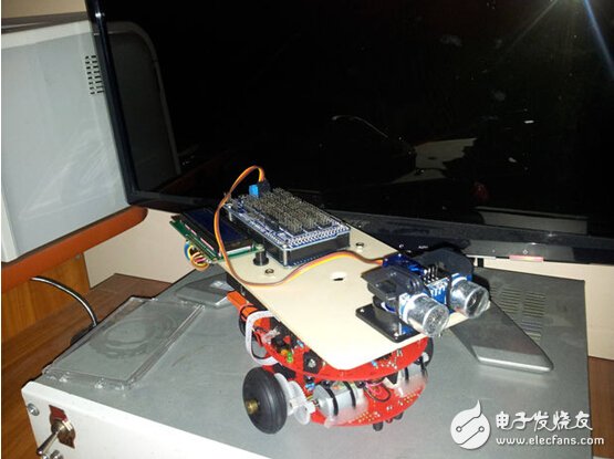
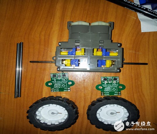
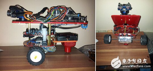
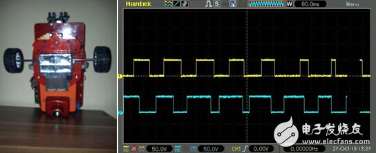
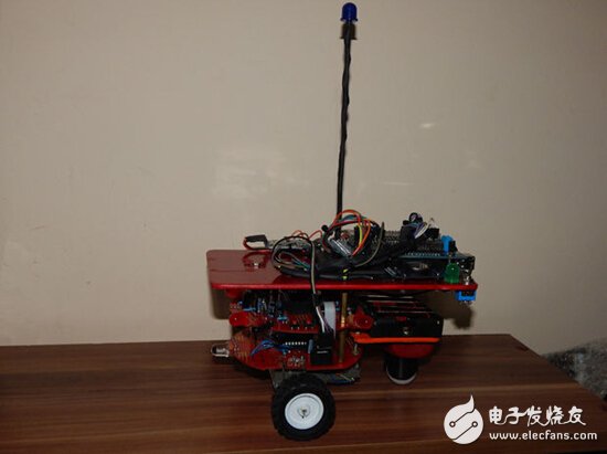
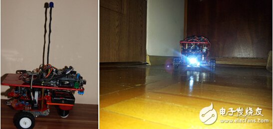
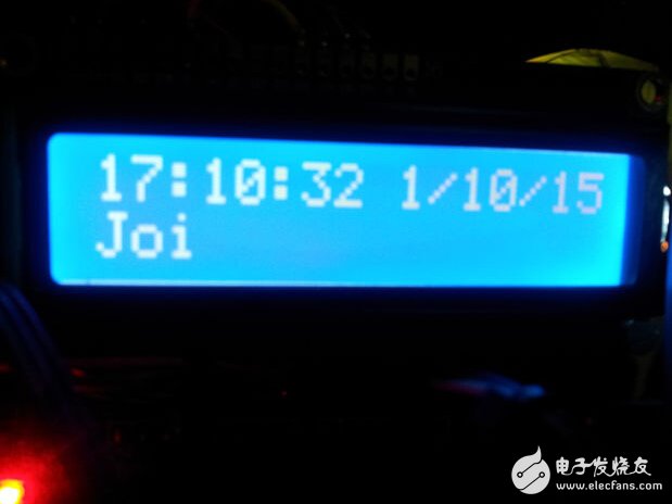
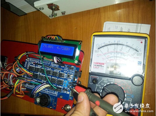
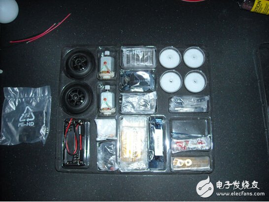
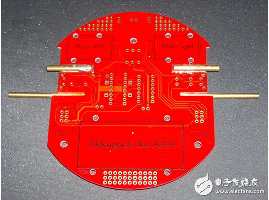
First buy a robot component from the website. This is a good starter and the price is right. When assembled, the original design was flawed, so the original design could be improved by making an experimental platform. Why should I improve the original design? - Infrared sensors are not accurate enough. - The odometer module does not work. - The wheel does not have enough traction. - 128 Microcontroller is based on Atmel interface / L - low power AVR 8-bit IC, very powerful, but poorly designed, proprietary frequency and pin. -- The programming language is Compact-C: based on the C language, but there are many additions. The programming IDE service is full of loopholes. - It has only a single I2C expansion port. It lacks the average Arduino expansion capability. - Wheel and gear rods are soldered to the board; this is a huge drawback. If you are not careful, you will weld at a different angle, thus changing the stepping of the gears, resulting in different wheel speeds. In addition, any weld can be easily broken, the traces fall off if you accidentally touch it, or it falls down, such as from your desk. Step 1: Building the original equipment - These LEDs are small, 3 mm, you can't even notice them. - Gears bend in time (right center): Decent construction, poor material (plastic). - You must use hot glue to keep the position of the motor. - Low battery capacity (4 x AAA) battery. Although this is a low-powered robot, the battery is not that much. - The robot balance uses two parts of table tennis. This is a poor design of implementation, due to the high friction with almost all surfaces, the low ground clearance is close, and the wet plastic material will deform when pressure is applied. At the same time, these table tennis balls are half hot and stick to the pcb, and the appearance looks cheap and ugly. - You have to press the start button, reset the button, then release the reset, then boot it into programming mode. This is really annoying. In the picture you can see the components, mcu, all the parts I used to build the original device. It takes about 2 to 4 hours to complete the build, because you have to carefully install the components, don't leave the wrong space, and then repeat everything. Step 2: Improve stability These table tennis are slowing down the robot's decline because of the high friction on all surfaces it passes. They also reduced the ground clearance. The first test can use an office chair wheel and a piece of cardboard. The office chair wheel is too large, causing problems in the direction when it is reversed. But the idea is good. The next test is a different platform, more flexible, made of plastic. Alternatively, you can use a smaller one. But then you will find that the back of this platform build robot covers the battery, you can't move them unless you disassemble the entire platform, so install the battery pack on the top of the platform. The small wheel also has the same problem, such as the office chair wheel: it changes the direction of the robot, which is a very bad thing. The solution is to replace the small wheel with a ball caster to solve the problem of direction. Next upgrade the 4 x battery pack AA battery instead of the 4 x AAA battery. This battery can last 4-5 times the AAA battery. In addition, switch from a normal battery to a nickel-metal hydride rechargeable battery. Step 3: Replace the microcontroller and expansion board The expansion board is not very useful, so it can be removed. Then you can add a piece of plastic and paint it in red (so it will match the main color of the robot). The following are added to the plastic plate: Arduino large 2560 Kai 3 (Chinese clone uses CH340) ——Sensor 2560 giant board Bluetooth HC-06 module - 16 x02 LCD RTC module ——On/Off switch ——Pro micro servo 9 g SG90 mounting bracket and ultrasonic sensor bracket ——HC-SR04 ultrasonic sensor Use the old MCU socket arduino board to run the wires. Light-emitting diodes, motors, speakers, microphones and AREF pins have been used so far. To-do list: Infrared sensor. It looks like a big messy wire, but this is the whole point of view: an experimental platform! You can access anything on the plug and use it. When the project is almost done, you can do some line management. Step 4: Replace the original drive system Replaced the original drive system gearbox-type system. Now that the car works independently, the weight (load) of the robot does not affect the shaft, it can be easily configured in 4 different ratios. To modify the axes, because they are too short. Lay some 3 mm rods from the previously cleaned parts and old printers. They are made of steel, made of some strange metal of 3 mm original hexadecimal, which is easily broken when the power is high. The inner part is in the d style, and a glue stick is used. The wheel has a crest and a rotary encoder. Wheel and pinion box motors, rotary encoders are designed to be modified with gearbox mounting. Connect the motor, encoder, and test them with an oscilloscope. However, there are minor failures in the software, and they can be counterproductive from time to time. Step 5: Add casters, antennas and larger LEDs. Line management. The casters are lightweight and help the robot balance. The antenna can be used (from copper to thick wire - 1.5 mm diameter) so it's cool though not a practical use. But there is actually a use, you can try to connect it to the Bluetooth module's pcb antenna, by soldering the jumper from the newly built pcb antenna. Everyone can be surprised to see a huge push. Without the antenna, the Bluetooth module stops working at 2 m and the wall between the laptop and the robot. Test it from 20-25m and it works without any problems. Remove the Bluetooth status SMD LED and replace it with a 10mm LED antenna. Shield the wires along the Bluetooth module from the LED with the heatshrink tubing. Add a 10 mm green LED to the on/off switch, at the top of the board, and replace all 3 mm LEDs with 10 mm LEDs. The opposite red LED is used for the line module on the original equipment, with a 10mm white LED, to make some light when you need it most (at night, poor lighting, etc.). Step 6: RTC module test Uploading a sketch to Arduino seems to be very good. Use the RTC module as part of the event-driven parameter logger. Step 7: AREF voltage monitoring tool This is an experimental battery monitoring system used to detect the capacity of the battery pack. Step 8: Implement the odometer. Drive on a predefined path. This is a test using an odometer system, the robot drive triangle. In addition, 5 cm on a piece of paper. Step 9: List - Solar panel rechargeable battery. - Predefined path telemetry time events. - Object avoidance and terrain mapping. ——The flashing system uses led to display the path of the robot Ic Sockets,Ic Sockets Connector,Ic Straight Pin Socket Connector,Round Pin Ic Sockets Connector Dongguan ZhiChuangXing Electronics Co., LTD , https://www.zcxelectronics.com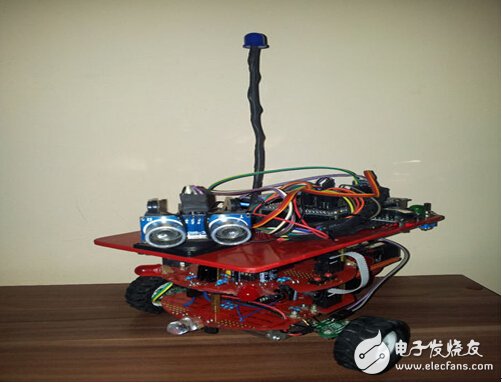

This article is selected from the electronic enthusiast "Security Technology Special", more quality content, download now
