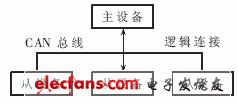
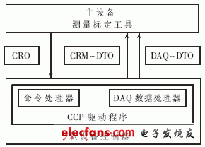
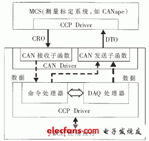
At present, the distributed system based on CAN (Controller Area Network) bus is widely used in the field of automotive electronics, and the calibration of the electronic control unit has become an important link in the development of automotive electronic control devices. CCP (CAN CalibraTIon Protocol) is a CAN bus-based ECU (Electronic Control Unit) calibration protocol [1], which has been applied in many European and American car manufacturers. Using the CCP protocol can quickly and effectively achieve the calibration of automotive electronic control units . However, the calibration based on the CCP protocol requires the implementation of a CCP driver within the ECU. At present, most applications use the free CCP driver provided by Vector [2]. Considering that the implementation of the ECU bottom program and the CAN driver are different, it is not a one-time thing to integrate the CCP driver into the ECU [3], which requires the CCP protocol itself, the calibration tool, and the calibration tool and the ECU The communication has a detailed and in-depth understanding. In the development process of the entire calibration system, a lot of time was spent on the combination of the early CCP driver and ECU. Based on a brief introduction to the CCP protocol, this article provides an example of the combination of a generic ECU and CCP driver to help shorten the entire calibration development cycle. CANape [4] is an ECU calibration and test tool. Combined with the CCP protocol, it not only can complete the calibration of the ECU, but also can directly access the memory and operate during the operation of the ECU. This makes CANape not only a powerful calibration tool, but also a powerful assistant for the development of electronic control units. However, in terms of use, the early configuration of CANape is relatively cumbersome, and currently there are few relevant materials in China. This article will introduce CANape and focus on how to use CANape to complete the ECU calibration based on the CCP protocol. 1 CCP protocol and working principle The CCP agreement is an integral part of the ASAP (Arbeitskreis zur Standardisierung von ApplikaTIonsSystemen) logo. ASAP, as an application system standardization working group, aims to provide common software and hardware interface standards to solve the problem of interface mismatch due to controllers provided by different manufacturers. 1.1 CCP communication method The ECU calibration based on the CCP protocol uses a master-slave communication method, as shown in Figure 1. The master device is connected to multiple slave devices through the CAN bus, where the master device is the measurement calibration system MCS (Measurement CalibraTIon System), and the slave device is the ECU that needs calibration , In automotive electronics is the on-board controller. Figure 1 CCP communication According to the CCP protocol, the master device first establishes a logical link with one of the slave devices, and then initiates data communication between the two through the master device sending commands to the slave device. When the master device wants to access another slave device, it first disconnects the logical connection with the current slave device and establishes a new logical connection with the next slave device before starting communication. 1.2 Working mode of CCP protocol CCP defines two working modes: Polling mode and DAQ (Data AcquisiTIon Command) mode. In the query mode, each communication between the master device and the slave device is initiated by the master device sending a command. After receiving the command from the master device, the slave device performs the corresponding operation and feeds back a frame of message. This kind of working mode requires the "one question and one answer" information exchange between the host and the slave, so the working efficiency is not high, but the implementation is simple, and the ECU memory resources are small. The DAQ mode enables the slave device to escape the command control of the master device and automatically upload data to the master device at a certain period. In DAQ mode, the master device first sends a command requesting DAQ. After receiving it from the device, it configures and organizes the data to be uploaded according to the parameters in the command, and then uploads the data to the master device autonomously in a certain period. This mode does not require the host to be controlled step by step through commands, and the work efficiency is high, but the implementation is more complicated. If the amount of data to be uploaded is large, it will occupy a large amount of ECU memory space. 1.3 CCP message frame structure The calibration based on the CCP protocol only occupies two frames of CAN messages, which are Command Receive Object (CRO) and Data Transmission Object (DTO), as shown in Figure 2. The CRO is sent from the master device to the slave device, and the DTO is a message fed back from the slave device. Both are identified by their own ID identifier (CRO_ID and DTO_ID). Figure 2 CCP protocol master and slave device communication The ID identifiers of CRO and DTO are defined by the communication protocol. The CCP protocol only defines the data fields of CRO and DTO in detail. According to the CCP protocol, the first byte of the CRO data field is the command code CMD (Command Code). The CCP protocol specifies a total of 28 commands [1]. The slave device uses the CMD code to determine which command the master device is requesting. The second byte of the data field is the Command Counter (CTR). The remaining 6 bytes are all command parameters, and each command has its own corresponding command parameters. The message returned from the device is called DTO. According to the CCP protocol, DTO is subdivided into three categories: · Command Return Message (CRM): feedback message sent by the slave device for CRO. Event Message (Event Message): When the slave device detects an internal error mechanism, the slave device sends it to the master device, reports its current operating status, and requests the master device to suspend the current work process to deal with the error. · DAQ-DTO (Data Acquisition-DTO): used in DAQ mode, organized by the slave device and sent to the master device regularly. The first byte PID (Packet ID) of the DTO message defines the type of DTO, 255 stands for CRM, and 254 stands for event message. The second byte is Command Return- / Error Code (ERR). For CRM, the master device learns the execution status of the command from this byte; for event messages, the master device learns from the bit what kind of error occurred in the slave device. The third byte CTR is the command counter, and the value of this bit corresponds to the CTR value of its corresponding CRO. The remaining 5 bytes are the data field, which stores the data or information requested by the master device. 2 Interface program realization based on CCP protocol Based on the CCP protocol for calibration, applications that require MCS and ECU can support the CCP protocol. This part of the application is called CCP driver. This article uses the free CCP driver provided by Vector [2]. Because the CCP protocol is based on the CAN bus, the combination of the CCP driver and the ECU is mainly divided into two aspects with the CAN driver and other applications. The combination of CCP driver and CAN driver is shown in Figure 3, which is mainly divided into the following two aspects: Figure 3 CCP calibration program interface · Sender: DTO uploads to MCS in CAN message format through CAN driver's sending sub-function. · Receiving end: The command sent by the master device first enters the receiving sub-function of the CAN driver in the format of CAN message. After it is judged as CRO, it is further handed over to the command processor. As a main component of CCP driver, the command processor is responsible for interpreting the received CRO through its CRM code, performing corresponding operations, organizing feedback data and calling CAN sending sub-functions. The DAQ processor supports the DAQ working mode. When the command processor judges that the received command is a DAQ request, it further transmits the data to the DAQ processor. The DAQ processor organizes the data and directly calls the CAN sending sub-function. The form is regularly uploaded to the main device. CAT6 Lan Cable performance is superior to iso11801-2002, TIA/EIA568C.2 and GB50311-2007, and it has passed the test of third-party authoritative institutions and obtained UL certification
Different flame-retardant grades of materials can be used for outer sheath materials.
Cat6 Lan Cable,Cat6E Ethernet Cable,Flat Cat6 Ethernet Cable,Outdoor Lan Cable Cat6 Shenzhen Kingwire Electronics Co., Ltd. , https://www.kingwires.com


Backward compatibility, downward-compatible CAT5e and lower categories of systems, to avoid user investment losses
Low transmission delay, compact cable design, reduce cable distortion and knotting during installation
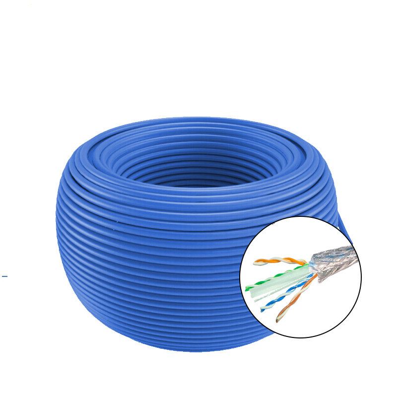
The center PE cross frame ensures that the twisted pair is not damaged during the installation to the greatest extent, and has high anti-electromagnetic interference, so that the bit error rate of the transmitted signal is reduced to the lowest degree.
Built-in tearing rope, easy to construct.
Mark, cable number, cable class, cable gauge, fire rating, standard, meter number and lot number are printed on the outer sheath of cables.
The inner axle and outer carton are packed, and the outer carton is pasted with certificate of quality.
The production process of insulated single line adopts on-line control eccentricity, on-line spark detector, on-line water capacitance detector and other on-line equipment to ensure the high reliability and consistency of the products. The color code of insulated single line adopts color strip to meet the environmental protection requirements.
All materials made of copper, PE and PVC have been tested and analyzed, and the content of radioactive harmful heavy metals has been completely controlled within the strict international standards.
Insulation layer material is high density polyethylene (HDPE).
