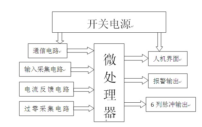
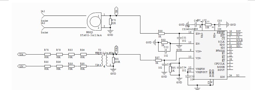
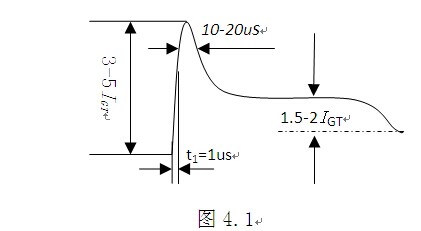
Wuhan Huida Industrial Control Technology Co., Ltd. three-phase control trigger board is based on advanced industrial-grade single-chip microcomputer and power transformers, pulse transformers, combined with peripheral devices to achieve three-phase SCR control, half-controlled bridge trigger control, using the lock The phase-loop technology and the zero-crossing triggering method realize the synchronization of the trigger pulse and the power signal (line voltage), improve the anti-interference ability of the trigger, improve the symmetry of the three-phase trigger pulse, and generate different orders by software control. 6 sets of trigger pulses, adapt to different nature loads, high control accuracy, and good dynamic characteristics. Pulse asymmetry ≤0.1°, triggered by military pulse transformer, the steepness of the pulse front ≤0.2uS, dual-screen digital display, function, parameter setting using key operation, fault, alarm using LED display, simple and convenient operation, intuitive display . First, characteristics l It adopts wide power supply and can provide the display panel to complete the character man-machine operation interface. The input signal fault indication and the input and output can be configured to facilitate user use and maintenance. l Multi-function combination alarm, alarm delay, prevent malfunction, over-temperature auto-off output, over-current alarm, start-disconnect alarm, or cancel this function. l The A/D acquisition is stable, and the temperature drift treatment is automatically eliminated. The parameters can be modified, and the power loss can be automatically memorized. l Suitable for many types of thyristor triggering, a variety of different load connection modes, with configurability. l Soft-start soft-off function can be arbitrarily configured, and can be manually output when external resistance is applied. l Support standard Moudbus-RTU protocol, RS485 hardware interface. l 60 ° pulse column triggering mode, good stability, strong anti-interference ability; output with anti-burn protection. Second, the principle of control 2.1 overall design diagram 2.2 Core Circuit Description This circuit is NZK-M series SCR three-phase trigger module current feedback circuit, IA1, IA2 termination of the current transformer (HWGS-3B5A/2.5mA) secondary winding, the primary load current, feedback current is changed by the current transformer Than after the current feedback circuit and microcontroller processing. Third, the load of conventional control theory 3.1 Transformer Control 1) The design capacity of the transformer is insufficient, causing the transformer core to saturate when the current increases to a certain extent, resulting in a sharp increase in current, waveform distortion, and damage to the device. The transformer must be redesigned or the maximum current limiting function must be added. 2) In the course of operation, power is turned off after a momentary power failure, etc., causing a "crash" in polarity and remanence polarity (inherent remanence and deceleration of the magnetic field when the power is turned off) at power-on, resulting in a dangerous impact voltage, Current. Therefore, inductive loads, especially transformers, should be powered by a slow start, and gradual paramagnetic and gradual turn off gradually attenuate the magnetic field. 3) Transformer is inductive load, narrow pulse trigger is not reliable. Pulse width variable DC triggering technology can provide enough time for the load current to reach the thyristor rush current, ensuring reliable triggering. Note: The transformer load cannot be adjusted and run without load. 3.2 pure metal 1) Silicon, molybdenum, molybdenum wire, tungsten, platinum, graphite, etc. load cold resistance is small, low pressure and middle temperature require pressure limiting and current limiting; as temperature increases, resistance increases linearly, but load voltage needs to be increased in high temperature section. . The current limiting function of the SCR three-phase phase shift/zero crossing trigger module is designed specifically for this type of load. In addition, meters with multiple sets of PID and regulation output limits can also control the load current. For example: The company's XMA-55 series instrumentation or Island Power's FP21, etc. can be designed to adjust the output limit of the low, medium and high temperature areas. 3.3 silicon carbon rod 2) Generally use slow start> 1 minute or longer and current limit, avoiding negative resistance impulse current near 700°C (new rod is more obvious). 3.4 Constant resistance (refers to the load with small changes in thermal resistance) 1) The control strategy is relatively simple, zero-crossing mode can be used to overcome the shortcomings of low power factor and polluting power grid. Cycle zero (duty cycle control) is generally implemented using high-power SSR. With zero-cycle tuning, the load current is evenly distributed in units of full sine waves. When multiple devices are in operation, the total power current is relatively balanced (the current zero-cycle current concentration is avoided), the furnace temperature uniformity is improved, and the ammeter striker is avoided. The important thing is: to improve the power utilization and avoid the capacity expansion of power equipment, the power-saving effect is very obvious. Three-phase thyristor phase shift / zero trigger module is thyristor power regulator integrated design, both adjustable pressure can also be adjusted (period and zero cycle two ways), to meet different control strategies. Fourth, SCR trigger theory The thyristor needs to have a certain trigger signal on the control electrode from turn-off to turn-on. The trigger signal can be a DC, AC signal or a pulse signal, but usually the pulse signal is used. 4.1 Thyristor Triggering Circuit Basic Requirements 1) The trigger signal should have enough trigger power (voltage and current), the general trigger voltage is 4-10V, and the trigger current is several tens to several hundred milliamperes. Therefore, the primary DC supply voltage of the pulse transformer is required to be not less than 15V (usually 18-24V) 2) The average power of the control pole should not exceed the permissible value. For a 5A thyristor, it should be less than 0.5W, and 10-50A should be less than 1W. 3) The trigger pulse should have enough width because the turn-on time of the thyristor is about 6us, so the trigger pulse width can not be less than 6us. 4) When using strong triggering, the thyristor control pole power may exceed several times the allowable average power, but the allowable peak power is much larger than the average power. Because the triggering time of the thyristor is very short, the strong trigger pulse can be very strong. Narrow, commonly used strong trigger pulse waveform is as follows: T1=1us 1.5-2IGT 10-20us Figure 4.1 5) In order to make the trigger time accurate, it is necessary to trigger the rising edge of the pulse to be steep, preferably below 10 μs. 6) With anti-jamming capability, the output voltage of the trigger circuit should be less than 0.15-0.2V when triggered. To avoid false triggering, a negative voltage of 1-2V may be added to the control pole if necessary. 7) The trigger pulse must be synchronized with the supply voltage applied to the thyristor to ensure that the conduction angle of the thyristor in the main circuit is equal in each cycle, and it is required that the timing of the trigger pulse can be smoothly moved back and forth (that is, the phase angle), At the same time, it is also required that the phase-shift range be wide enough 4.2 common pulse trigger Depending on the type of load, you can choose from 6 different types of pulse triggering, as follows: 1) narrow pulse: its pulse width T = 30-100us, suitable for resistive load and low power thyristor, as shown in (a) 2) Wide pulse: its pulse width T = 100us-5ms, suitable for inductive loads, according to the strength of the inductor to select the appropriate pulse width shown in Figure (b), weak inductive load, can be selected 1ms or less, strong inductive load, can Select 1-5ms, for three-phase full-control bridge circuit, if not using double-pulse triggering, in order to enable the two thyristors with phase sequence to be triggered at the same time, the pulse width must be greater than 60° electrical angle, generally about 5ms. 3) Continuous pulse: its pulse width T=180°-α (Α is the thyristor conduction angle), suitable for strong inductive loads, as shown in (c) iG 180°-α 30-100us iG 100us-5msM iG Figure (a) Figure (b) Figure (c) 4) Double-pulse: Double-pulse is mainly used to meet the requirements of three-phase full-bridge circuit, so that two adjacent components can get the trigger pulse at the same time, as shown in figure (d) 5) Pulse train: The carrier frequency is 5-20kHz. Pulses of any width can be adjusted into pulse trains to simplify the transmission of pulses, as shown in Figure (e) 6) Combination pulse: When triggering series or parallel thyristors, it requires a very high rising rate of the trigger current, such as (1-3) A/us. When the pulse width is wide, the number of pulse transformer turns must be high, and the leakage inductance is large. It is difficult to achieve a very high rate of current rise, as shown in Figure (e). For this purpose, a narrow pulse and wide pulse combination with a high rate of rise must be used. iG 60° iG iG V. Summary All control parameters of the trigger board are digital, no temperature drift changes, stable operation and reliable operation. Strong anti-interference ability, using unique measures, bad interference to the normal operation of the environment. Versatility, wide application range, trigger board to adapt to any nature of load, manual, automatic; steady flow, voltage regulator; potentiometer control, module control can be arbitrarily selected and switched, adapt to more than six large-scale control of thyristor components Rectification equipment. Has complete failure, alarm detection and protection. Real-time detection of over-current, over-voltage, and internal board failures. With boot soft start, emergency stop soft-off protection. Easy to debug, trigger board debugging without oscilloscope and multimeter. Each trigger board undergoes rigorous software testing and hardware aging to ensure stable and reliable operation. Main application areas: salt bath furnace, industrial frequency induction furnace, quenching furnace temperature control; heat treatment furnace temperature control; glass production process temperature control; diamond press heating; Pressure Regulating; Vacuum Magnetron Sputtering Power Supply; Textile Machinery; Crystal Stone Production; Powder Metallurgy Machinery; Tunnel Electric Kiln Distributing Temperature Control System; Color Picture Tube Production Equipment; Metallurgical Machinery & Equipment; AC & DC Motor Drag; Petrochemical Machinery; Current, power, light and other stepless smooth regulation, constant voltage constant current constant power control and other fields. In order to meet different levels of demand, we are strengthening the development of new products and constantly introducing new ones. In order to meet your special requirements, we are willing to customize for you. When you use our products, you may find some unsatisfactory places. Please send your valuable comments. We would like to express our heartfelt thanks.
The speaker wire harness most are used in automobile, house applicance ,audio,video,radio,fuse wire ,game
machine.Yacenter has experienced QC to check the products in each process,
from developing samples to bulk, to make sure the best quality of goods. Timely
communication with customers is so important during our cooperation.
If you can't find the exact product you
need in
the pictures,please don't go away.Just contact me freely or send your sample
and drawing to us.We will reply you as soon as possible.
Speaker Wire,Custom Speaker Wiring Harness,Speaker Wiring Harness,Car Speaker Wire Harness Dongguan YAC Electric Co,. LTD. , https://www.yacentercns.com


