Direct Driven Servo Motors,Direct Drive Motor,Ac Motor Integrated Servo,Ac Three Phase Servo Motor Zhejiang Synmot Electrical Technology Co., Ltd , https://www.synmot-electrical.com
The responder achieves the function of digital display answering with only two digital chips through a very clever design. Compared with other responder circuits, it has the advantages of extremely short resolution time, simple structure, low cost, convenient production, etc. Anti-cheating feature.
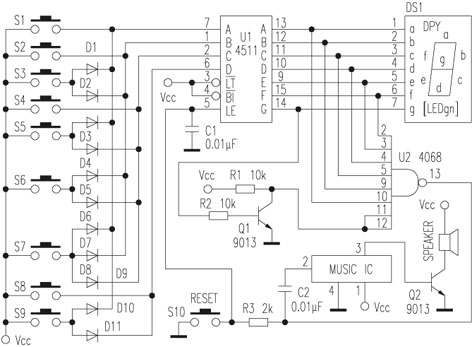
The principle is shown in the attached drawings. 
S1~S9 are 9 answering buttons, CD4511 is BCD code 7-segment decoder, CD4068 is eight-input NAND gate, and VD1~VD11 acts as BCD encoding for light touch buttons. In the initial state, the CD4511 drives the LED digital tube to display 0, that is, the six strokes A, B, C, D, E, and F are 1, and the G stroke is 0. Now the G stroke signal is inverted by the triode, the stroke signal corresponding to 0 is changed to all 1, and then these stroke signals are sent to the eight input NAND gate CD4068. According to the logical relationship between the NAND gate and the NAND gate, the CD4068 output is 0, so that the 7-segment decoder CD4511 is in the decoding state. Since the stroke signals corresponding to the numbers other than 0 are not all 1, the CD4068 cannot be outputted 1, and the 7-segment decoder CD4511 is not in the decoding state. Therefore, when a button is pressed, the CD4068 outputs a latch signal 0, causing the 7-segment decoder CD4511 to latch the entered digital display. The button that is pressed after this will not work. Only the first pressed key number is displayed on the digital tube. Played a role in answering questions.
R1 and C1 form an integration circuit to make a very short delay on the latch signal. The function is to allow the digital circuit to have sufficient response time to make the latch stable and not to display garbled characters. The role of C2 is to turn the DC trigger into a pulse trigger, so that the music circuit only rings once per rush. S10 is the reset button. This button can be pressed before the host calls "Start". If the S10 button is not displayed as 0, it means that someone is cheating, which shows which number is who is cheating.