Solar System Batteries,60Ah Ni-Fe Battery,24V Nickel Iron Battery Bank 60Ah,Ni-Fe Battery 10~80Ah Henan Xintaihang Power Source Co.,Ltd , https://www.taihangbattery.com
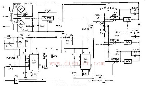
The circuit is as shown. AN0 is the start button switch, K1 is the "working" and "stop" selector switch, K2 is the "manual" and "automatic" operation selector switch, K1 is the 5 step and 7 step selector switch, AN1 ~ AN7 is K2 in the manual position It is a manual operation button switch. IC1~IC7 use 555 to form 7 single stable time circuits (the IC2~IC6 circuits are the same, not shown in the figure), respectively to illuminate LED1~LED7 LEDs and 7 thyristors. The rectifier 3CT1025 controls the seven solenoid valves DF1 to DF7 to perform mechanical actions. The IC8 is a seven-input or gate, and the output terminals connected to the seven input terminals are connected to the input terminals of IC1 to IC7.
Just turned on. The voltage of the 4th pin of IC1~IC7 rises in time, which ensures that the zero level is output before starting AN0, and no malfunction occurs. At this time, IC8 also outputs zero level, and DF1~DF7 do not operate (no current). Click on AN0. First, IC1 is triggered to output a high level to make LED1 light, DF1 is powered up, and IC8 output high level to ensure that AN0 no longer works. IC1 timing 1.1RC output lower jump pulse trigger IC2, analogy until IC5 (K3 at 1-5 position) or IC7 (K3 at 1-7 position) output timing 1.1RC high level, so that DF1 ~ DF7 in turn, Finally, the IC8 outputs back to the low level, in preparation for the next sequential control process for the AN0 to start again.
IC1 to IC7 correspond to the operating time of each segment of DF1 to DF7, and are determined by the timing resistance RC of each of IC1 to IC7. The practical range of R is approximately 5 to 10 MΩ, and the practical maximum value of C is approximately 1000 μF. Therefore, the timing of each step can be arbitrarily set within tens of minutes or even hours. The actual sequence control takes anywhere from a few seconds to a few minutes, which is easy to implement.
The manual process is not described here. Just put K2 in the manual position and manually operate AN1~AN7.
DF1 ~ DF7 use DC 36V solenoid valve. The operating voltage of 555 is 5V supplied by the regulator W7805. The power transformer needs to use the secondary output 10V.30V two windings, the 10V group current 0.3A or more is enough, the 30V group needs a large current to drive DF1~DF7. 