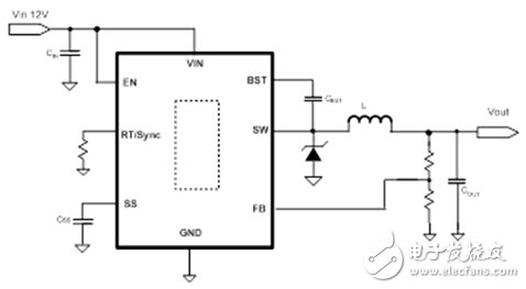
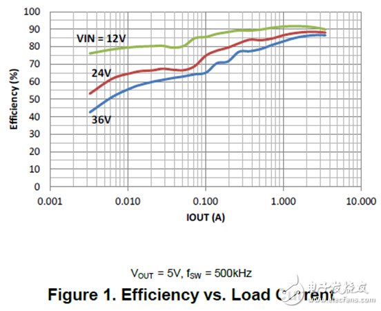
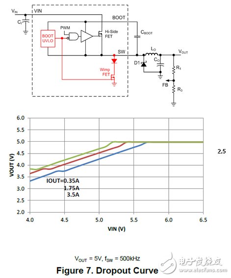
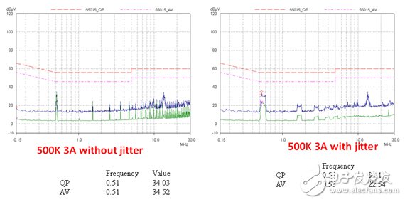
Simple Switcher, as its name implies, is translated into Chinese as "Easy Power". In 1989, simple switcher introduced the first generation LM2576. The chip integrates MOS tube, peripheral control and compensation circuit. The peripheral circuit is very simple, no need for customers to spend too much time designing and Debugging, popular with customers, is popular all over the world. It is still widely used in many industrial customers. After more than 20 years of development, simple switcher has launched many generations of products. This article mainly introduces the 5.5th generation of Simple switcher, and analyzes its characteristics and parameter indicators in detail. This product can be widely used in industries, automobiles and communications. background With the growing development of customer systems such as industry, automotive, and communications, new demands have been raised, such as miniaturization of products, low power consumption, and low dropout. The old products of LM2596 and LM2575 are gradually unable to meet the requirements. The 5.5th generation products are produced under such a background. The series is a 40V withstand voltage product, a total of three product numbers, LMR14020, LMR14030, LMR14050, the corresponding current is 2A, 3.5A, 5A, in SO8 package. Figure 1 shows its typical application circuit. Compared with the previous products, it not only maintains the characteristics of being easy to use, but also has more features and better performance in the 5.5 generation. Mainly reflected in the following aspects. 1. Simple switcher 5.5th generation product performance Wide voltage input The demand for wide voltage input is becoming more and more common in industrial and automotive applications, with 31% of applications withstand voltages up to 40V. So much of the wide voltage demand comes from the following aspects. One: the system itself is a wide voltage input, such as the thermostat working input voltage is 24V, the working voltage range is 18V-32V; Second: the car or truck battery powered system, the normal working voltage is 12V or 24V, but in the toss When the load is applied, the voltage may reach 30V or more, and the voltage will even drop to about 5V during the cold start process, and the voltage range changes very wide. Third: the elevator control system, the power supply input line is very long, at the moment of system startup, due to parasitic inductance The presence of LDi/dt causes a very high peak voltage. Four: The engineer will leave some safety margins, derating the components and so on. The 5.5th generation of Simple Switcher covers a range of 4V to 40V input voltages, making it ideal for power applications in industrial and automotive applications. Static operating current In recent years, the concept of “green environmental protection†has become popular. On the one hand, the energy supply pressure brought by population growth, on the other hand, the environmental problems brought about by the energy exploitation process. More and more industrialized countries are generally aware of the importance of energy conservation. Sexuality, many countries have begun to implement “green policies†to encourage manufacturers to introduce energy-saving technologies in their end products. . In the case of a DC/DC converter, energy saving means higher conversion efficiency and lower standby power consumption. . In addition, in the automotive field, quiescent current also has an effect on the battery. The larger the quiescent current, the faster the battery energy consumption. The battery is the only energy provider for cold start of the vehicle. If the energy is consumed too much, the vehicle may not start properly. European car OEMs typically require a 6-8 week standby period, which means they can start the car normally within 6-8 weeks. The DC/DC power supply needs to maintain standby operation after the vehicle is turned off. The main power supply requirements mainly come from two aspects. . First, the function needs, such as the electronic clock's travel time (time) circuit; the remote control circuit's receiving part. Second, the need for fault diagnosis, in order to quickly solve the vehicle fault, the current vehicle has a diagnostic function, that is, the controller can identify the cause of the fault and store it in the controller in the form of code. The 5.5th generation of Simple Switcher products only absorb 40uA in sleep mode, which is very suitable for battery-powered equipment and some energy-saving and environmentally friendly systems. As shown in Figure 2, the efficiency of 12V to 5V at 10mA is 80%, and the performance is excellent. Minimum on time The input and output conversion formula of the Buck circuit is Vout=DVin, D is the on-duty ratio, and the corresponding on-time is ton=D/fs. High frequency has always been an important trend in the development of switching power supplies. On the one hand, high frequency can reduce the demand for inductance and capacitance, and meet the needs of miniaturization and low cost of customer products. On the other hand, many automotive customers need to have a power switching frequency above the AM band in order to avoid interference from the power supply to the AM band. . Take the 2MHz switching frequency as an example. If you need to convert 12V to 3.3V, the theoretical on-time is 137.5ns. In other words, only when the controllable conduction time of the chip is lower than 137.5 ns, the output can be properly regulated. . The simple switcher 5.5th generation has a minimum on-time of 75ns, which is very suitable for high-frequency applications. In other products, this indicator is also excellent. Maximum duty cycle As mentioned in the previous section, the input and output conversion formula of the Buck circuit is Vout=DVin. In theory, if D=1, Vout=Vin. However, under actual circumstances, it is difficult to achieve a 100% duty cycle because the built-in MOS transistor drive circuit cannot make the MOS transistor always turn on. Most of the internal integrated N-MOS power chips require a bootstrap capacitor to provide the energy to drive the N-MOS turn-on. Cboot is the drive storage capacitor as shown. Capacitor charging takes time. When the duty ratio is large and the lower diode conduction time is short, if the energy of the Boot capacitor is not full, then the Mos tube cannot be reliably turned on in the next cycle. In this case, the output is Unstable or large shocks. So in some chips, the maximum duty can only be about 80%. In the process of voltage start and voltage drop, when the input is close to the output, the application of the chip is limited. In the simple swithcher 5.5th generation, the maximum duty cycle can be 97%. The working principle is as shown in the figure below. A small Wimp Mos tube is integrated inside the chip, and the Mos tube does not work normally during normal operation. When the input is close to the output, if the voltage on the Boot capacitor drops to a certain voltage, the Mos tube will be forced to conduct for a short period of time, so that the voltage on the Boot capacitor returns to the rated value. The figure shows the measured results. In the case of low dropout, the output is very good for tracking the input without any voltage fluctuations. EMI EMI is a problem that often plagues power engineers, and many experienced engineers sometimes have nothing to do with it. Engineers often need to solve EMI by using larger filters (increasing costs) or by reducing MOS tube switching speed (increasing switching losses). . The 5.5th generation of Simple switcher provides a frequency-jitter function (optional). When the system EMI is too late to solve, you can try the frequency-jitter function, and the EMI problem may be solved soon. As shown, the improvement in the frequency of the jitter is obvious. in conclusion Through the introduction of the simple swithcher 5.5th generation product, in addition to the simple and easy to use this biggest feature, its product performance is also very excellent, to meet the various needs of industrial and automotive customers, the perfect solution to ease of use. Balance with high performance. Specific parameter design can refer to the corresponding data sheet, and our online simulation tool Webench can provide schematics, bills of materials, simulation and design files, saving customers a lot of time and cost. headphone transformer,smoke alarm transformer,refrigerator low frequency transformer,potted transformer IHUA INDUSTRIES CO.,LTD. , https://www.ihua-inductor.com


