0 overview 1 Demand analysis In order to ensure the statistical analysis of teaching management electricity load and real-time monitoring of dangerous sources, it is necessary to conduct real-time online monitoring of the voltage, current, power and other parameters of the high and low voltage distribution cabinets of the school substation once the monitoring points are displayed The parameters are abnormal, and alarms can be issued in time, and the relevant personnel take necessary measures to avoid the occurrence of safety accidents. The automatic meter reading function saves manpower and material resources, and the current trend curve function can intuitively display the working status and time of each circuit, which is convenient for users to find abnormal power circuits and make timely corrections. Acrel-3000 power management system has high safety and reliability, easy to expand, and easy to repair and maintain. 2 System solution Acrel-3000 power management system According to the actual situation of Qilu University of Technology, the overall network structure uses shielded twisted pair to connect directly to the serial server of the power distribution station and then directly to the monitoring host of the monitoring room, which guarantees the power of the power distribution station. Management system transmission stability and real-time. As shown in the following figure: station control management layer, network communication layer and field device layer. System structure diagram Schematic diagram of communication line connection 3 System functions The real-time monitoring system diagram of the power distribution station is the main monitoring screen, which mainly monitors the running status of all circuits of the power distribution station in real time. In the system diagram, you can intuitively see the operating parameters and status of each incoming and outgoing line, and you can see all the conventional power parameters on the outlet side of the transformer, such as: three-phase voltage, current, active power, reactive power, power factor , Frequency, active power, etc. As shown below: Primary system diagram of power distribution station Meter reading Energy report Schematic diagram of communication structure The trend curve can visually check the load operation of the loop. View the real-time and historical trend curves, and click the corresponding button or menu item on the screen to complete the corresponding function switch; help the user to analyze the trend and recall the fault, and have the curve printing function. It provides intuitive and convenient software support for analyzing the running status of the entire system. As shown below: Trend graph references: About the author: You Xiaoyun, female, undergraduate Ankerui Electric Co., Ltd., whose main research direction is smart grid power supply and distribution Email: Mobile QQ
ZGAR TWISTER Disposable
ZGAR electronic cigarette uses high-tech R&D, food grade disposable pod device and high-quality raw material. All package designs are Original IP. Our designer team is from Hong Kong. We have very high requirements for product quality, flavors taste and packaging design. The E-liquid is imported, materials are food grade, and assembly plant is medical-grade dust-free workshops.
Our products include disposable e-cigarettes, rechargeable e-cigarettes, rechargreable disposable vape pen, and various of flavors of cigarette cartridges. From 600puffs to 5000puffs, ZGAR bar Disposable offer high-tech R&D, E-cigarette improves battery capacity, We offer various of flavors and support customization. And printing designs can be customized. We have our own professional team and competitive quotations for any OEM or ODM works.
We supply OEM rechargeable disposable vape pen,OEM disposable electronic cigarette,ODM disposable vape pen,ODM disposable electronic cigarette,OEM/ODM vape pen e-cigarette,OEM/ODM atomizer device.
Disposable E-cigarette, ODM disposable electronic cigarette, vape pen atomizer , Device E-cig, OEM disposable electronic cigarette ZGAR INTERNATIONAL(HK)CO., LIMITED , https://www.zgarette.com
The construction site of Qilu University of Technology Heze Campus is north of the North Outer Ring of Heze City, east of the planned Botanical Garden, west of the planned Mudan Road and south of the Ridong Expressway. The total planned land size is 1435 mu, of which the project covers an area of ​​1204 mu, with a total construction area of ​​470,000 square meters and a total investment of 2.4 billion yuan. The project will be completed in two phases. The first phase will be built with 6,000 students and 568 acres. The second phase will reach a scale of 15,000. All the projects will be completed by the end of 2018.
This project undertakes its power management system for substation and distribution, including one 35 / 10kV substation and four 10 / 0.4kV substations. The monitoring host is located in the monitoring room of the 35 / 10kV main station.
Data collection Automatically collect analog data of all power meters on site, and automatically collect on-site data such as on-off status and fault status.
Support real-time collection, automatic cycle collection (timed collection) configurable cycle (1 minute to 24 hours).
Support multi-thread processing mechanism, improve data collection efficiency, and can collect data from multiple devices at the same time.
The real-time data display adopts the visual display mode of the main wiring diagram of the power distribution room, and the circuit breakers are closed and the fault status is visually visible.
Data analysis and processing The comprehensive statistics and analysis of data need to realize the following functions:
Statistics and calculations of power consumption data of each device within the time period of hours, days, months, and years. Count the electricity consumption of each substation and the whole.
The data query and display requirements can facilitate the realization of client queries and queries of managers at all levels. The query interface can meet the requirements of managers at all levels. It can support flexible conditional combination query and comparative analysis. Various statistical analysis data can be flexibly used in reports Intuitive display functions such as various charts.
According to the different permissions of different users, the data display function is divided into three layers: operation layer, management layer, and decision layer.
Privilege management It is required to grant different users with different roles, which can be authorized to function sub-menus, specific file records, data records, etc.
The system requires a reasonable and perfect user security control mechanism, which can effectively protect the information resources in the application environment and prevent the loss, theft and destruction of information.
Parameter setting The transformer ratio of each loop and various current and voltage protection setting values ​​can be set through the collection cabinet.
Fault judgment and alarm has the function of automatic fault judgment and sound and light alarm. The alarm types include switch failure, voltage and current overrun, communication failure of the field acquisition module, and communication failure with the monitoring system. The alarm time is automatically recorded in the system database, which is convenient for users to query. The staff can always grasp the real-time operation status of the substation, find the fault of the substation operation and deal with it accordingly, improve the management efficiency of the substation, improve the safety of the power system, reliability. 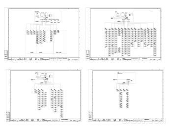
There are 18 PZ80-E4 / CK incoming power meters and 494 AMC72L-E4 / CK outgoing power meters in the on-site substation, and a total of 17 RS485 buses are connected to the four serial servers of the substation. The serial server directly passes through Cat5e cable or fiber is connected to the monitoring host in the monitoring room.
1) Station control management station The station control management layer is a direct window for human-computer interaction for the management personnel of the energy management system. In this project, it refers to the industrial control monitoring host placed in the monitoring room in the substation.
2) Network communication layer The communication layer is mainly composed of 4 serial server, Ethernet equipment and bus network. The main function of the serial port server is to monitor the on-site intelligent instruments; the main function of the Ethernet equipment and bus network is to realize the data interaction between each power distribution room and the main station, so that the distribution system management is centralized, informatized, and intelligent. The safety, reliability and stability of the power distribution system are improved, and the purpose of unattended operation is truly achieved.
3) Field equipment layer The field equipment layer is a data collection terminal, which is mainly composed of intelligent power meters. The intelligent equipment uses a MODBUS communication protocol bus type to access the serial server through the shielded twisted pair RS485 interface, and reaches the power distribution room through the communication server for monitoring The host computer performs networking to realize remote control.
The on-site connection of the smart device indicates that the field device connects by hand in hand through the shielded twisted pair (RVSP2 * 1.0). Each bus is connected to about 20 smart devices. Different types of smart devices are connected to different buses. The data is uploaded to the serial server, and then the data is uploaded to the industrial control computer in the monitoring room. The specific connection diagram is as follows: 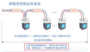
0.4kV incoming circuit adopts PZ80-E4 / CK multi-function intelligent instrument, and outgoing circuit adopts AMC72L-E4 / CK intelligent instrument. Both are network power instruments designed for the power management needs of power systems, public facilities and intelligent buildings. , Can measure all conventional power parameters, such as: three-phase voltage, current, active power, reactive power, power factor, frequency, active power, reactive power.
All intelligent devices can be transmitted through the bus to meet the data exchange requirements with the monitoring host. 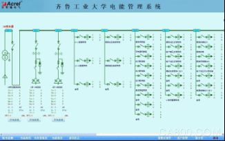
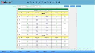
The parameter meter reading function mainly inquires into the electrical parameters of the low-voltage outgoing circuits. Supports electrical parameter query at any time, with functions such as data export and report printing. This report queries the electrical parameters of each low-voltage loop of the transformer inlet and outlet lines of the power distribution station of Qilu University of Technology, mainly including: three-phase current, active power and active power. The circuit name of this report is associated with the database, which is convenient for users to modify the circuit name. As shown below: 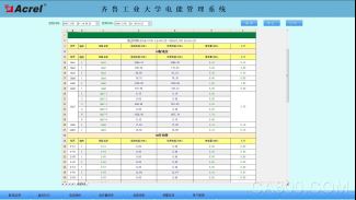
Electricity consumption report function, you can select the time period to query, support the cumulative query of electricity in any time period, and have the functions of data export and report printing. Provide accurate and reliable electrical energy report for duty personnel. The circuit name of this report is associated with the database, which is convenient for users to modify the circuit name. As shown in the figure below, the precise power consumption of the distribution circuit is displayed. The user can print the report directly or save it to another location for other purposes. As shown below: 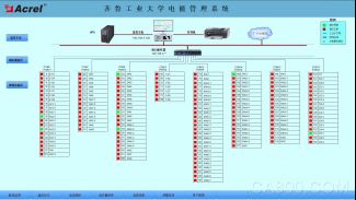
Schematic diagram of the system communication structure, which mainly shows the network structure of the system. The system adopts a hierarchical distributed structure and monitors the communication status of the equipment at the bay layer. Red indicates normal communication, green indicates abnormal communication. The figure below is a schematic diagram of the communication status of the substation. 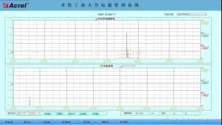
4 Conclusion In the application of current power distribution facilities, the power distribution safety of public college building complex projects is very important. The application of Acrel-3000 power management system introduced in this article in Qilu University of Technology can realize the supply and distribution of power distribution facilities The real-time monitoring of electrical circuit power consumption can not only display the status of circuit power consumption, but also have network communication functions. It can be combined with serial server and computer to provide electrical energy management functions. The system can analyze and process the collected data and display real-time power distribution The operation status of each distribution circuit, and generate various energy reports, analysis curves, graphics, etc., which is convenient for remote meter reading, analysis, and research of electric energy. The system is safe, reliable, and stable, providing analysis and monitoring of college electricity consumption Real and reliable basis.
[1]. Ren Zhicheng Zhou Zhong. Principles and Application Guide of Electric Power Measurement Digital Instruments [M]. Beijing. China Electric Power Press. 2007. 4
[2]. Edited by Zhou Zhongzhong. Product selection and solution of smart grid user-end energy management and energy management system [M]. Beijing. Machinery Industry Press. 2011.10

