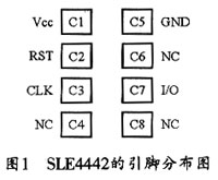
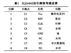
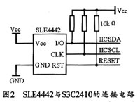
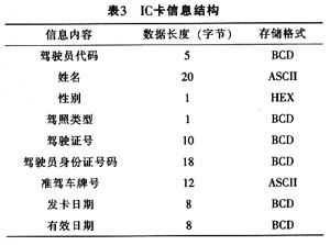
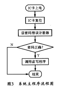
introduction This article refers to the address: http:// In recent years, with the development of the economy and the improvement of people's living standards, cars have entered more and more people's lives. However, traffic accidents are frequent and car driving safety has become a problem. The use of car tachographs plays an important role in curbing traffic accidents such as fatigue driving and vehicle overspeed, restraining the driver's bad driving behavior, ensuring vehicle safety and regulating vehicle management. To regulate driver behavior, as one of the basic functions of the car tachograph, it should first be able to accurately identify the driver's identity. The unit using the car tachograph should be equipped with an IC card for each driver, and the driver should log in with the IC card when he leaves the car. The recorder mainly confirms the driver's unique identity by reading the IC card. The IC card management module in the PC management software is mainly used for legal identity registration of the driver's IC card, and the user can edit the identity information of the driver in the card, including functions of erasing, writing, and reading. 1 design choice At present, the driver identification method adopted by the vehicle driving recorder mainly includes two methods of non-contact IC card recognition and contact IC card recognition. The writing process of the non-contact IC card recognition system is usually performed by radio waves that are not contacted by the IC chip and the reading and writing device. The operation process of the non-contact type 1C card identification mode is relatively simple, but the anti-interference ability is relatively weak, and the cost is high. When the CPU in the contact type IC card recognition system detects the insertion of the IC card, it immediately reads the data through the I/O port of the card, and then judges and processes the program. After determining the legal IC driver IC card, the driver information is retrieved according to the agreement. The contact type IC card has a large storage capacity, and the writing machine has a low construction price and is relatively convenient to maintain. In this design, the application environment of the car tachograph is considered to be complicated. The non-contact IC card is susceptible to electromagnetic interference from the car ignition, and the storage capacity of the driver identity data is not satisfactory. Therefore, the contact type of the design option 2 is selected. IC card identification method to set the juice. 2 Hardware design of the driver identification system 2.1 IC card chip selection The general-purpose memory chips currently used for IC cards are mostly EEPROMs, and the commonly used protocols mainly include a two-wire serial connection protocol (I2.C) and a two-wire serial connection protocol. The logically encrypted memory card can use cryptographic control logic to control access and rewrite to the EEPROM memory, so it can be copied or overwritten as arbitrarily as a memory card. In the design, since the driver identification requires security and confidentiality, this design selects the logical encryption memory card SLE4442 designed by Siemens as the IC card storage chip. The SLE4442 has 2KB of storage capacity and a completely independent Programmable Security Code (PSC) memory. Its internal voltage boost circuit ensures that the chip operates at a single +5V voltage, while its large memory capacity meets the requirements of typical applications. Therefore, SLE4442 is an IC card chip that is widely used in China. The main features of the SLE4442 card chip are as follows: â—‡Multi-memory structure, including three memories: 256x8-bit EEl, ROM-type main memory, 32xl-bit PROM-type protected memory and 4x8-bit EEPROM-type encrypted memory: â—‡Using a 2-wire connection protocol, the serial interface satisfies the IS07816 synchronous transmission protocol; â—‡ NMOS process technology, each byte of write, erase programming time is 2 5 ms; â—‡ has at least 104 writes, erase cycles, and data retention times of at least 10 years. The distribution of the terminals of the SLE4442 memory chip is shown in Figure 1. Table 1 lists the pin function descriptions. 2.2 IC card hardware interface circuit SLE4442 is a 2-wire connection bus mode, in which I/O is a serial data line. This pin is an open-drain drive and can transmit data in both directions. It is mainly used for input and output of address data. The CLK pin is the clock, which is the synchronous clock signal for device data transmission. The microcontroller in this car tachograph uses the S3C2410, which contains an I2C bus controller that can be easily connected to various devices with an I2.C interface. In the design, the IICSDA, IICSCL and RESET of the main controller are connected to the I/O, CLK and RST of the IC card respectively. The bus is controlled by the microcontroller, and the serial clock can be controlled by the program to control the access of the bus and then send. START and STOP signals. The interface circuit diagram of SLE4442 and S3C2410 is shown as in Fig. 2. 3 IC card I2C transfer protocol The heart transfer protocol is a two-wire connection protocol between the interface device and the IC card integrated circuit. The data change on the SLE4442 chip l/O line is valid only on the falling edge of the CLK signal. The I2C transfer protocol includes four modes: reset and reset response, command mode, output data mode, and processing mode. 3.1 Reset and reset response The reset response is based on the ISO/IEC 7816-3 (ATR) standard and can be reset at any time during operation. Initially, the address counter is set to 0 with a clock pulse. When the RST line changes from a high state (H state) to a low state (L state), the contents of the first data bit (LSB) are sent to the I/O. If 32 clock pulses are continuously input, the contents of the first 4 byte address units in the main memory will be read. On the falling edge of the 33rd clock pulse, the I/O line is turned high and turned off. Both the "start" and "stop" states are ignored during the reset response. 3 2 command mode After resetting the response, the chip will wait for the command. Each command starts with a "start state". The entire command consists of 3 bytes. This is followed by an additional pulse and ending with a "stop state". During the high state of cLK, the falling edge of the I/O line is the start signal: during the high state of cLK, the rising edge of the I/O line is the stop signal. 3.3 Output data mode In this mode, the IC card chip will send data to the external interface device. On the falling edge of the first CLK pulse, the first bit of data on the I/O line becomes active. When the last data required is sent, an additional clock pulse is required to place the I/O line in a high-impedance state (Z state) in preparation for receiving a new command. Any "start state" and "stop state" are masked during output data. 3.4 Data Processing Mode In the data processing mode, the system will internally process the IC card chip. During the entire process, the I/O line is locked to a low state and any "start state" and "stop state" will be masked. 4 system software design Each operation command of the SLF4442 chip contains 3 bytes. The order and operation format are listed in Table 2. The transmission of the command always starts from the control byte, and the lowest bit LSB of the byte is transmitted first (ie, B0 bit). After the control byte is transmitted, the address byte and the data byte are sequentially transferred, both of which are low. After the last bit (D7) transfer is complete, an additional clock pulse is required to set the I/O line high. The driver's identity information is stored in the 224 bytes (application data area) of the IC card's main memory, occupying a total of 83 bytes, and the remaining bytes are 0. The address is from 32 (20H)-255 (FFH). The data readout is not limited, but the erase and write need to check the password. After the password is successfully verified, the chip's encryption control logic will open the chip's master. Memory to allow subsequent erase and write operations. Its information storage format is listed in Table 3. Figure 3 shows the main program flow chart of the system. 5 Conclusion As an IC card memory chip, SLE4442 can be easily connected to a microcontroller with I2.C bus, and has the characteristics of cheap structure, safe and confidential, flexible use, simple circuit design, convenient maintenance and strong anti-interference ability. It is suitable for the working environment and characteristics of the car tachograph, so it has good application value in the car tachograph. Pure Line Interactive UPS,Pure Sine Wave,Dsp Control,Lcd Display Shenzhen Unitronic Power System Co., Ltd , https://www.unitronicpower.com