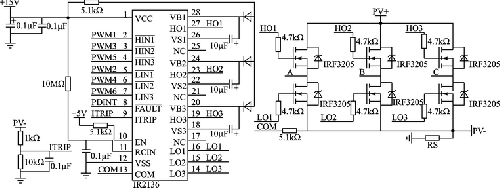
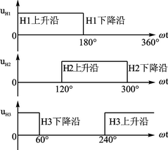
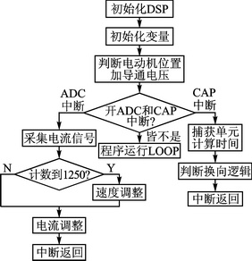
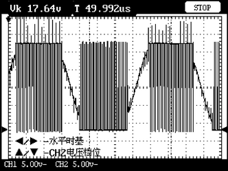
introduction This article refers to the address: http:// For a long time, electric motors have been widely used in various fields as a conversion device for mechanical energy and electric energy. The brushless DC motor combines the advantages of the DC motor and the AC motor. It has the characteristics of simple structure, reliable operation and convenient maintenance of the AC motor, and has the advantages of high operating efficiency and good speed regulation performance of the DC motor. It is these advantages that make brushless DC motors widely used in many areas of the national economy today. The brushless DC motor adopts an electronic reversing device, and according to the position signal detected by the position sensor, a certain logic control PWM waveform is generated by the DSP (Digital Signal Processor) to drive the motor to realize smooth running of the brushless DC motor. In recent years, with the rapid development of industry, the requirements for product performance have also increased year by year. For some modern products, simply controlling one motor can no longer meet the demand. It is necessary to control multiple motors to work in coordination and orderly to meet the functional requirements. The design uses TI's TMS320F28335 as the processor to drive two brushless DC motors in the form of driver chips and MOSFETs. On the basis of the completion of the hardware design, according to the different control methods of the software design, the motor can be driven synchronously or according to a certain rule. 1 dual motor synchronous control system The control object is two three-phase DC brushless motors with rated power of 3 kW and rated speed of 1 500 r/min. It is mainly used to control the two motors to run synchronously when synchronous walking is required. The control system of the DC brushless motor is mainly composed of a control part, a driving and Inverter circuit part, a rotor position detection and a current sampling circuit. Among them, the control part with TMS320F28335 as the core is responsible for controlling operations, analog sampling and other tasks; the driving circuit power-amplifies the weak electric signal outputted by the control circuit, and outputs a strong electric signal with a certain driving capability to control the switching tube of the inverter circuit. The DC inverter is converted into the motor to achieve the purpose of controlling the motor; the position detecting part detects the motor rotor signal and sends it to the control part for processing; the current sampling part completes the detection of the DC power bus current. The peripheral system has fewer peripheral devices, which reduces the design difficulty and improves the accuracy of the system by using high-performance sensor detection. 2 control system hardware design 2.1 System power supply design Different peripherals of the TMS320F28335 require different voltages, a core voltage of 1.8 V and an I/O voltage of 3.3 V. The power-up sequence also requires the I/O voltage to precede the core voltage, so it is necessary to design a power supply that meets the requirements of the control system. Using TI's TPS767D318 as the power chip, the input 5 V voltage is converted to 3.3 V and 1.8 V as the power input of the DSP; while the brushless DC motor voltage is 24 V, and the corresponding driver chip voltage is +15 V or -15 V, this uses the DC/DC module to convert the 5 V voltage to +15 V or -15 V as the power supply for the driver chip. In this way, the entire system only needs to supply 5 V and 24 V to meet the demand. The peripheral circuit of the TPS767D318 is shown in Figure 1. Figure 1 Peripheral circuit of TPS767D318 The DC/DC module is shown in Figure 2. Figure 2 DC / DC module Figure 3 driver chip IR2136 and MOSFET tube peripheral circuit design 2.2 driver chip and peripheral circuit design The brushless DC motor replaces the mechanical commutation of the DC motor by electronic commutation, and energizes the different phases of the motor to drive the motor to rotate. From the comparison of performance and cost, the more common method is the three-phase star full control bridge circuit. The on/off state of each phase of the brushless DC motor at each moment is determined by obtaining the phase position signals of the Hall sensors of the brushless DC motor itself. The DSP chip generates a certain regular PWM waveform signal according to the setting, and the driving chip amplifies the PWM signal output by the DSP, and outputs a signal with a certain driving capability to control the switching tube in the inverter circuit. The inverter circuit is composed of a power semiconductor device MOSFET, and the control logic signal required by the output motor drives the motor to rotate. The driver chip IR2136 and the MOSFET tube peripheral circuit are shown in Figure 3, where PWM1~6 are waveform signals from the DSP, and A, B, and C are respectively connected to different phases of the motor. 2.3 Detection system design of control system The PWM signal outputted by the driving chip IR2136 controls the switching transistor circuit to be turned on and off with a certain rule, so that different phases of the brushless DC motor are energized at different times. In order to be able to understand the parameters of the motor in real time during operation and to ensure that the motor operates under normal conditions, the operating state of the motor must be detected. The signals to be detected include phase signal signals, current signals, and voltage signals. The circuit is designed below for various signals that need to be detected. 2.3.1 Position signal detection There are three Hall sensors on the shaft of the brushless DC motor, each of which produces an output signal of 180° pulse width to indicate the position of the motor at each moment. The output signals of the three sensors have a phase difference of 120° with each other, and the position signal of the brushless DC motor is as shown in FIG. This produces six rising or falling edges in each mechanical revolution, which corresponds to six commutation times. Use the CAP function of the TMS320F28335's EV module (set to double edge trigger) to obtain each edge that needs to be commutated, thus controlling the motor commutation, and connecting the output position signal to the CAP pin port to achieve the corresponding function. Figure 4 Position signal of brushless DC motor 2.3.2 Current signal detection During the operation of the motor, only two phases are energized each time (one phase is positively energized and the other is energized in the opposite direction), so only one current needs to be controlled at a time, and the current feedback can be realized by placing the resistor on the ground to the ground. Supervision. The output of the current feedback is filtered and amplified and sent to the ADC port of the DSP for processing. The current is sampled every PWM period to control the speed (PWM duty cycle). Here, the output waveform is processed by the linear isolation amplifier HCNR200. The current signal detection circuit is shown in Figure 5. Figure 5 current signal detection circuit 2.3.3 Voltage signal detection During the operation of the motor, the DC bus voltage of the motor needs to be detected so that it is within the rated voltage of the motor. The A/D sampling of the DSP is used to understand the overvoltage or undervoltage condition of the motor. The voltage signal detection circuit is shown in Figure 6. Figure 6 voltage signal detection circuit 2.4 Other peripheral circuit design In order to enable the entire control system to operate, other peripheral circuits are also required, such as DSP clock circuits, reset circuits, JTAG circuits, RS232 circuits, and extended design of DSP function ports. In some important places, it is necessary to add indicator lights to facilitate understanding of the operation of the control system. Due to the high frequency characteristics of the DSP system, electromagnetic compatibility issues need to be considered during design to make the entire system work properly. 3 system software design The final implementation of the control tasks in the control system is done by software. Therefore, based on the completion of the hardware design, the software must be designed. The quality of the application directly determines the quality and efficiency of the entire control system. Motor control is generally a fast process that requires a series of software processes to be completed in a certain amount of time. For example, the feedback signals of the motor controlled parameters (speed, current, voltage, etc.) are sampled, calculated and judged and processed accordingly. In order to meet the real-time requirements of the system, the control system needs to use the interrupt mode to monitor the real-time input and output. The software design makes full use of the interrupt processing capability of TMS320F28335 to complete tasks such as current sampling, position capture and PWM waveform generation. The ADC completes the sampling of current and voltage, and the CAP completes the capture of the position signal and the determination of the commutation logic. The software task mainly includes the main program and each interrupt subroutine, and the flow is shown in Figure 7. Figure 7 system control software flow According to the software and hardware design of the control platform, after debugging, the motor runs smoothly. The phase voltage of a phase during operation is shown in Figure 8. Figure 8 Phase voltage diagram when the motor is running 4 Conclusion This paper proposes a hardware design scheme for a universal dual-motor control platform, using TI's TMS320F28335 as the main processing chip, and the highly integrated peripheral circuit design makes the circuit simple; using the rich peripherals of TMS320F28335 makes the system control performance better; The TMS320F28335 has two identical EV modules, so it is possible to control two motors simultaneously with one Controller, saving costs. On the basis of this control platform, combining the control system with the actual control strategy can realize different control functions and methods, and then apply to different occasions.
storage systems, Solar Battery generator, Portable Solar Power System, solar energy systems, mobile solar energy generator, solar power generator, solar energy generator
Portable Solar Power System lithium solar battery, solar portable generators, inverter portable solar generator, portable solar system, solar home system Delight Eco Energy Supplies Co., Ltd. , https://www.cndelight.com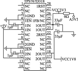



portable solar power system