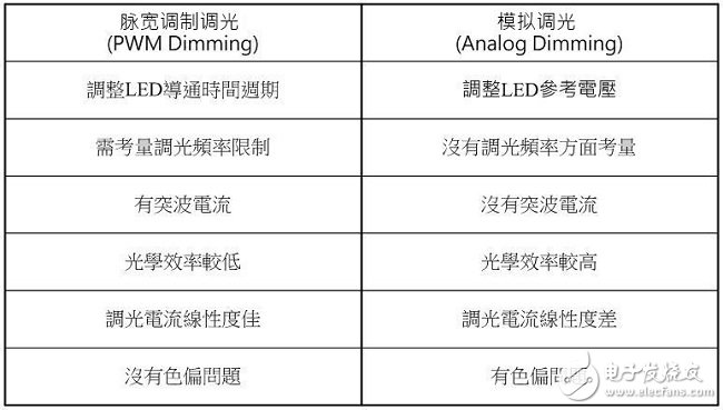
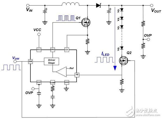
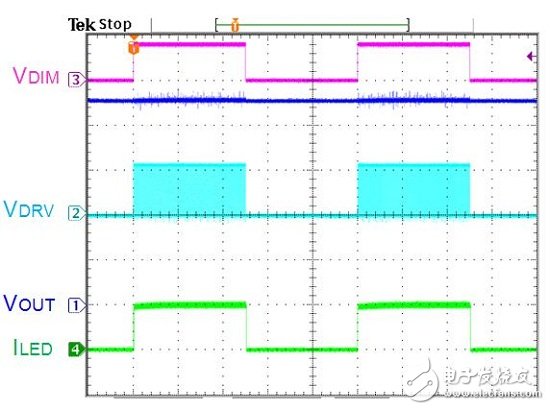
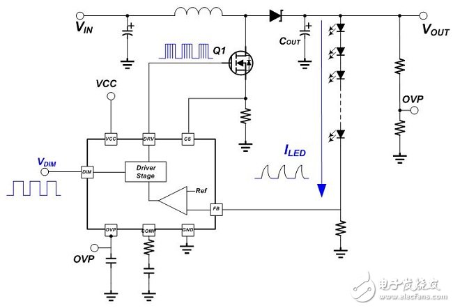
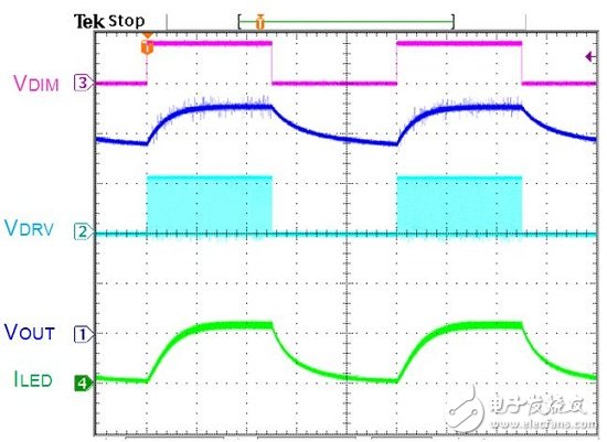
There are many ways to dimming LEDs. Depending on the application requirements of the system, there are different options. It can be divided into PWM Dimming and Analog Dimming depending on the LED output current waveform. Simply put, the so-called pulse width modulation dimming means that the output current of the LED is a periodic square wave output with LED conduction and LED non-conduction, and the average current of the LED is adjusted by changing the on-time width of the square wave waveform. Size, to achieve the function of dimming. Therefore, the average LED current value can be equal to the on-period of the square wave multiplied by the maximum current, that is, ILEDavg = Duty (%) & TImes; ILEDmax, as shown in Figure (1). Figure (1) Pulse Width Modulation (PWM Dimming) Analog dimming is the output current of the LED is an analog output waveform. By changing the level of the output current to adjust the current value of the LED, the function of changing the brightness of the light source is achieved, as shown in Figure (2). Figure (2) Analog Dimming If the input control signal of the LED dimming is taken into consideration, the input control signal according to the LED dimming and the difference of the LED output current waveform can be summarized into four configurations, as shown in Table (1). These different dimming control methods are applied to lighting, such as commercial lighting, office lighting, home lighting and other indoor lighting requirements, as well as backlights for displays or LCD TVs. System operators can choose the most optimized according to different product application specifications. Competitive dimming method. Table (1) LED dimming classification In the past, the backlight of the panel was CCFL with cold cathode lamp. Since the curve of current and brightness is not very linear, PWM dimming control is adopted. This trend has been used in the current LED backlight control, but not too much to simplify the architecture. The change, the dimming input control signal is maintained using PWM dimming, the dimming frequency is greater than 100 Hz digital signal, and the PWM output current waveform is digital or analog to define PWM dimming or analog dimming. Table (2) is a comparison table of characteristics of pulse width modulation dimming and analog dimming, which helps to understand the difference between the two characteristics. Table (2) Comparison of characteristics of pulse width modulation dimming and analog dimming In short, if you do not understand the characteristics and advantages and disadvantages of various LED dimming methods and the application of the actual system, it is not easy to find the correct dimming method. This article will present some analysis, through these analysis, to understand the LED dimming method and its advantages and disadvantages, you can choose the appropriate dimming method and LED driver IC application. (1) LED driver IC pulse width modulation dimming application (PWM Dimming) Figure (3) is a boost single-string LED current, pulse width modulation dimming application line. The DIM pin input signal is a pulse signal. In order to achieve the pulse waveform output, it is necessary to connect a power switch Q2 in series with the LED path. When the DIM pin input signal is high level, the driver IC starts to operate, and the magnetic component inductance is performed. The energy storage and release energy increase the output voltage enough to make the LED string turn on, and the dimming switch Q2 turns on (Turn On), so the LED output current is established immediately. Figure (3) Pulse width modulation dimming application line one When the DIM pin input signal is low, the driver IC does not operate, the output voltage cannot be established to turn on the LED string, and the dimming switch Q2 is turned off (Turn OFF), and the LED output current is synchronously cut off. Therefore, the pulse width modulation dimming application circuit (PWM Dimming) needs to add a dimmer switch Q2 in the path of the LED series to achieve a better pulse output. This pulse width modulation dimming method is to change the pulse conduction period, and can achieve a dimming raTIo of 1000:1, so it has better contrast between high and low brightness. Wide range of applications in current consumer electronics displays and LCD voltages. Figure (4) is a measured waveform, the input voltage is 20V, the voltage of the LED string is about 50V, the LED current is 500mA, and the LED current waveform at 1KHz / 50% dimming is compared with the voltage waveform of the boost switch Q1 Gate. It can be seen from the waveform that the LED output voltage ripple voltage is small, the LED current is a conduction/non-conduction current signal, and the LED driver IC DRV pin drive signal is a high-frequency switching period with the dimming signal being switched on and off. The high frequency and discontinuous output signals generated by PWM Dimming are prone to EMI, audio interference, and panel display ripple. Figure (4) Measured waveform one Figure (5) is a boost single-string LED current, pulse width modulation dimming application line. In order to save costs, the switch component Q2, which should be connected in series on the LED string path for dimming, is removed. When the DIM pin input signal is high, the driver IC starts to operate, and the magnetic component inductor is stored and discharged, and the output voltage is raised. However, as the output voltage is established, the LED string current starts to slowly turn on. . Figure (5) Pulse width modulation dimming application line 2 When the DIM pin input signal is low, the driver IC does not operate, and the voltage stored on the output capacitor COUT is slowly discharged through the LED string path. The current waveform of the LED in the dimming mode is a near-distorted pulse. The waveform is shown in Figure (6). Figure (6) Measured waveform 2 Omitting the dimmer switch assembly of the LED string, the biggest advantage of this application is that it can save cost, but provides a rough brightness adjustment, using the slower response of the eye vision as a filtering function, and the switching frequency of the line follows the dimming When the frequency is turned off, when the dimming frequency is Off, the LED still flows current, and the output voltage drops. When the dimming frequency is ON, the output voltage will not be enough to make the LED string fully conductive. The error amplifier inside the driving IC is bound to move. Inductive energy causes the output voltage to rise. In this way, the line characteristics will be sacrificed, the LED output voltage ripple will become significantly larger, and the LED output current is neither pulse output nor nonlinear output, so the linearity of the LED dimming current, the linearity of the LED average current and brightness will be poor. When the dimming period is small, there may be flickering, so the dimming period range is limited, and the contrast of the dimming is also significantly deteriorated. Problems such as EMI, audio interference, and panel display ripple are still present, so this is not a good way to dim. Network Accessories,Wifi Adapter,Fiber Optic Network Components,Splitter Fiber Optic Cixi Dani Plastic Products Co.,Ltd , https://www.cxdani.com


