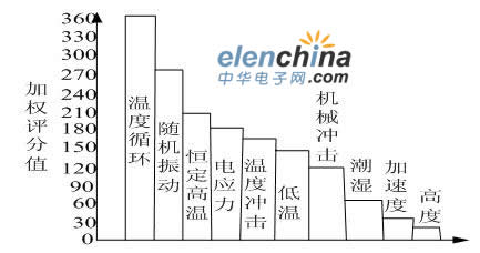
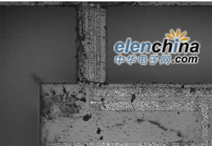
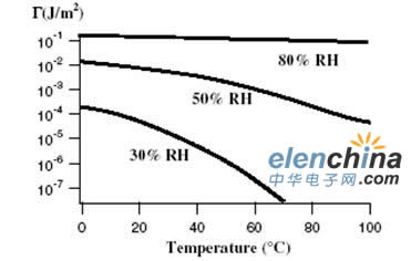
1 Introduction This article refers to the address: http:// For a long time, when people carry out environmental simulation test on products, most of them use the test method of single environment, that is, only one environmental condition is applied to one product at a time, such as single humidity test, single impact test, etc. Apply more than two environmental conditions to a product at a time. Practice has shown that a single environmental test method can not effectively screen out products with various potential defects in the development and production stages. That is to say, products with high reliability through single environmental test still have faults in use, and the actual The reliability is very low, the ratio of the former to the latter can reach 20:1 [1]. For more than ten years, foreign countries have been working on new environmental testing methods to improve product reliability. In China, in the concept of reliability enhancement test, the narrow concept of reliability intensification test can only be carried out on pneumatic test equipment, and the reliability test can be carried out by using conventional test equipment. . Figure 1 is a comparison of various stress-to-defect priming abilities in environmental stress screening. It is based on a limited survey of the screening effects of 10 stresses and has a certain representativeness. It shows that temperature cycling and random vibration are the most effective excitation stresses. The relationship between temperature, humidity and vibration is relatively close. On the other hand, these three kinds of environmental stresses have a long time and cause more damage. For example, a research report pointed out that in the total damage, temperature accounted for 40%, vibration accounted for 27%, and humidity accounted for 19% [2]. It can be seen that they account for a large proportion of the total number of device component destruction. Therefore, temperature cycle, humidity and random vibration are used as the most effective excitation stress for reliability test to truly and efficiently excite the potential defects of the micro accelerometer. Figure 1 Comparison of various stress excitation capabilities in environmental stress screening 2 Micro accelerometer failure mechanism in the combined environment of temperature, humidity and vibration Through the three comprehensive tests, it is found that the main failure mode of the micro accelerometer in the combined environment of temperature, humidity and vibration is the fracture and adhesion of the beam. 2.1 Effect of temperature on the failure of micro accelerometer A complete piezoresistive silicon micro-acceleration sensor is mostly composed of different materials, such as gold or aluminum, silicon and glass. These materials have different coefficients of thermal expansion. Once the temperature changes, compressive or tensile stresses are generated at the interface of different materials. This compressive or tensile stress belongs to the internal stress of the microaccelerometer. The internal stress of the accelerometer is increased due to the influence of ambient temperature conditions. The piezoresistive micro accelerometer studied in this paper is manufactured by bulk silicon process. The main processes include photolithography, thin film deposition, ion implantation, and wet and dry methods. Due to the influence of the processing technology, the processed micro accelerometer will inevitably have residual stress. The residual stress can be divided into tensile stress and compressive stress according to the direction, as shown in Fig. 2. Obviously the residual stress is also the internal stress of the accelerometer device. Figure 2 Residual stress in different directions Through the above analysis, it can be known that when the micro accelerometer is not affected by external environmental conditions, the internal stress of the device has only residual stress; and when the micro accelerometer is subjected to temperature stress, it is generated due to different thermal expansion coefficients of different materials constituting the device. New internal stresses. Therefore, the temperature stress deteriorates the influence of residual stress on the micro accelerometer to a certain extent, and increases the internal stress of the micro accelerometer. 2.2 Influence of vibration on the failure of micro accelerometer The main failure mechanism that causes the accelerometer to fail is that the stress generated by the vibration is greater than the yield strength of the accelerometer and the long-term vibration causes the structure to fatigue and fracture [3]. As the random vibration frequency increases, the response of the accelerometer becomes larger and larger, and the output of the accelerometer is larger. The short-time random vibration has almost no damage to the micro accelerometer. When the vibration time is prolonged, the micro accelerometer Fracture failure occurred at the cantilever beam, as shown in Figure 3. Figure 3 Vibration causes damage to the structure of the accelerometer 2.3 Influence of humidity on micro accelerometer Condensation of water vapor on the micro-planar surface leads to an increase in the residual stress of the structure [4]. If the two surfaces are close to each other, an increase in the relative humidity between them will result in an increase in the capillary force, which in turn causes the structure to deform, eventually causing the structure to adhere. Figure 4 Figure 4 Schematic diagram of accelerometer adhesion 2.4 Influence of three comprehensive stresses of temperature, humidity and vibration on the micro accelerometer In the comprehensive test of simultaneous application of temperature, humidity and vibration, from the mechanism of failure occurrence, the inside of the product subjected to temperature cycling expands and contracts due to the difference in thermal expansion coefficient of the material, and loose separation occurs at the joint portion [5]. At this time, if humidity is applied, moisture will invade from the gap, and the friction coefficient of the joint portion and the joint portion is lowered, so that the action of the joint surface can be increased because the surface interaction energy is related to the distance between the two surfaces, and therefore, The surface roughness of the two surfaces greatly affects the amount of surface interaction energy. The surface interaction energy decreases rapidly as the surface roughness increases. At the same time, the study also found that temperature and relative humidity have a great influence on the adhesion and surface interaction energy. It can be seen from Figure 5 that the surface interaction energy decreases with increasing temperature corresponding to different relative humidity. It can be seen from Fig. 6 that at high and low temperatures, the surface interaction energy increases as the relative humidity increases. At the same time, the vibration stress is applied, and the resonance phenomenon of the product occurs with respect to a specific frequency. Such an iterative process of moisture absorption, freezing, and resonance by motion makes it possible to introduce a new failure mode (caused by a single factor failure mode with a large acceleration and a superposition effect of three factors). Figure 5 Effect of temperature on surface interaction energy Figure 6 Effect of relative humidity on surface interaction energy Adhesion causes device failure to be ubiquitous. It refers to the phenomenon that two smooth surfaces adhere to each other under the action of surface forces when they are in contact with each other. The surface force referred to herein may be Van der Waals force, surface tension, capillary force, electrostatic adsorption force, and the like. Studies have shown that for hydrophobic surfaces, the dominant adhesion is the Van der Waals force. The adhesion caused by van der Waals' Wals force occurs in two close planes, not the surface of the contact, and changes abruptly as the square of the spacing changes. The capillary force plays a major role in the drying process after the corrosion release structure. In the processing and working process of MEMS, the mechanical movable member such as the micro cantilever can cause adhesion problems when the gap in the device is in the order of micrometer/nano. Adhesion can generally be divided into release-related adhesion and adhesion during use. Release-related adhesion means that the sacrificial layer is etched with hydrofluoric acid, and the polysilicon microstructure is released. When dry, the two sheets of hydrophilic, gap-on-micron/nano-sized silicon wafers are bonded due to the surface tension of the thin layer of water on the surface of the silicon wafer. In the bulk silicon dissolution process and various surface processes, when water or other liquids are dried and volatilized, two adjacent surfaces tend to be close to each other or even contact each other due to surface tension. Therefore, the adhesion here is related to water, the device is affected by moisture, and the adhesion work increases with increasing humidity. Resolving the release-related adhesions can be made by using an insulating film as an anti-adhesive film, while using a hermetic package, and it is moisture-proof and prevents particle contamination. However, the electrostatic accumulation of the insulating film may cause adhesion due to static electricity or intermolecular attraction. In addition to the surface tension of water, the chemical state of the silicon surface also has a great influence on the degree of adhesion between the microstructures: the surface oxide layer has a large thickness, a small water contact angle, a short beam separation length, and a large bonding force, which is easy to bond. On the contrary, adhesion is less likely to occur. In-use adhesion is a phenomenon of adhesion caused by the chemical state of the silicon surface. It occurs after the device is packaged. When the input signal is overshooted (by external force or actuation), the silicon is chemically affected by the surface of the silicon wafer. The sheet is bonded. Solution of adhesion problem The early method of reducing adhesion is to roughen the surface to reduce the actual contact area. The specific methods include: a long layer of thermal oxide layer, followed by dry etching. Now, the general method used is as follows 1) Non-adhesive design The stencil structure is designed on the bottom or side of the mechanical component. This reduces contact area and adhesion. 2) Supercritical drying Supercritical drying can be used during the structural release process to reduce the effects of adhesion. However, this method also has problems: the adhesion under environmental conditions such as structural release, impact, vibration, etc. is reduced, but under normal working conditions, mechanical components may come into contact with each other and adhere together, so that there is still failure. 3) Hydrophobic surface single layer A single layer of surface can be used to reduce the adhesion of the surface. The SAM cover film reduces surface adhesion energy by providing a passivation layer. 3 Conclusion The failure mechanism of micro-accelerometer fracture and adhesion under temperature, humidity and vibration stress conditions is analyzed. The three stress conditions are simultaneously applied to accelerate the exposure of the defects, which shortens the test time. Whether there are new failure modes under the three stresses of temperature, humidity and vibration remains to be studied. SHENZHEN CHONDEKUAI TECHNOLOGY CO.LTD , https://www.szsiheyi.com


