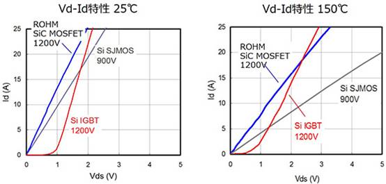
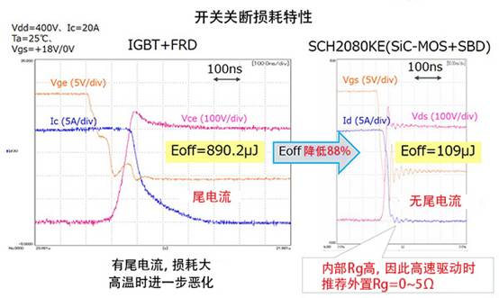
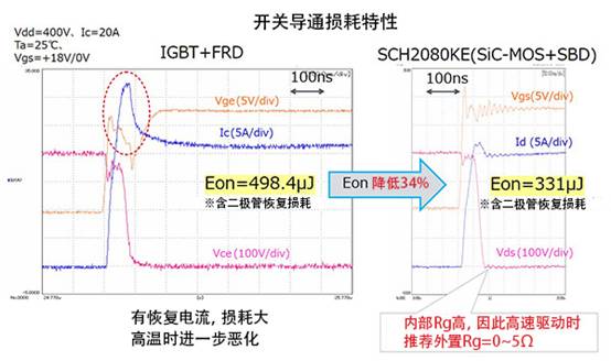
It is well known that the properties and advantages of SiC materials have been proven on a large scale and are considered to be ideal semiconductor materials for high voltage, high frequency power devices. The reliability of SiC devices is one of the focuses of development engineers, because there are no SiC-based devices in the presence of Si-based IGBT and MOSFET devices. SiC-MOSFETs are many different from IGBTs, but what is the difference between them? This article will introduce the difference between IGBT and IGBT. Difference from IGBT: Vd-Id characteristics The Vd-Id characteristic is one of the most basic characteristics of a transistor. The following are the Vd-Id characteristics at 25 ° C and 150 ° C. Please see the characteristic chart at 25 °C. The Id vs. Vd(Vds) of SiC and Si MOSFETs increases linearly, but since the IGBT has a rising voltage, the Vds of the MOSFET components are lower in the low current range (for the IGBT, the collector current, the collector-emitter) Voltage). It goes without saying that the Vd-Id characteristic is also an on-resistance characteristic. According to Ohm's law, the lower the on-resistance is, the lower the on-resistance is, the lower the slope of the characteristic curve is, and the lower the on-resistance is. The low Vd (or low Id) range of the IGBT (in the present example, the range of Vd to about 1V) is a negligible range in the IGBT. This does not pose a problem in high voltage and high current applications, but the efficiency of the low power range is not high when the power demand of the powered device is wide from low power to high power. In contrast, SiC MOSFETs maintain low on-resistance over a wider range. In addition, it can be seen that the slope of the characteristic curve of both SiC and Si-MOSFET is slowed compared with the characteristics of the Si MOSFET at 150 ° C, and thus the on-resistance is increased. However, the variation of the SiC-MOSFET at 25 ° C is small, and the difference in the characteristics of the product at 25 ° C is large, and the on-resistance of the SiC MOSFET changes little when the temperature is increased. Difference from IGBT: turn-off loss characteristics As mentioned many times before, SiC power components have excellent switching characteristics and can handle high power and high speed switching. Here, the difference from the IGBT switching loss characteristics will be specifically described. It is well known that when the IGBT switch is turned off, the tail current caused by the component structure flows, so the increase in switching loss is a basic characteristic of the IGBT. It can be seen from the waveform when the comparison switch is OFF that the SiC-MOSFET does not flow through the tail current in principle, so the corresponding switching loss is very small. In this example, the combination of SiC-MOSFET + SBD (Schottky barrier diode) is reduced by 88% compared to the turn-off loss Eoff of IGBT + FRD (fast recovery diode). It is also important that the tail current of the IGBT increases with increasing temperature. Incidentally, the high-speed driving of the SiC-MOSFET requires an appropriate adjustment of the external gate resistance Rg. Difference from IGBT: conduction loss characteristics Next, look at the loss when the switch is turned on. When the switch is turned on, the IGBT flows through the portion of the Ic (blue curve) with the red dotted coil. This is mostly due to the recovery current of the diode, which is a large loss when the switch is turned on. Remember: when using SiC-SBC in parallel, plus the fastness of the recovery characteristics, the loss of the MOSFET switch when it is turned on is reduced; the switch conduction loss when the FRD is paired increases with the IGBT tail current as the temperature increases. . In summary, the switching loss characteristics make it clear that SiC-MOSFETs are superior to IGBTs; SiC MOSFETs have also achieved the quality levels required for a wide range of industrial applications. In addition, the data provided here is the result of the ROHM test environment. The driving circuit and other conditions are different, and the results may be different. It is necessary to remember the specific analysis of the specific problem! Self Test GFCI Receptacle Outlet Self Test Gfci Receptacle Outlet,White Gfci Outlet,Smart Gfci Outlet,Gfci Power Outlet Lishui Trimone Electrical Technology Co., Ltd , https://www.3gracegfci.com

