Fiber Optic Distribution Box,Fiber Optic Breakout Box,Fibre Optic Breakout Box,Fibre Break Out Box Cixi Dani Plastic Products Co.,Ltd , https://www.danifiberoptic.com Part 2: So how bad is my grayscale?
Before we start to calibrate, we should go over it and see how far our grayscale is actually. This way we will have a good pre/post comparison. You will use ColorHCFR to read values ​​from 0 to 100 IRE, and we will use the readings of our Barco Cine 8 Onyx CRT projector as an example to explain the meaning of these charts.
Step 2.1 (Spyder 2 only): The Spyder2 sensor has some problems when reading low light like 10 and 20 IRE, so when we take our reading, we need to increase the reading time to 2000ms. To adjust this, select the menu option "Measures -> Sensor -> Configure" and set "Read Time" to 2000 ms, press "OK".
Step 2.2: Start the program by pressing the "Measure Grey Scale" button in the ColorHCFR form: 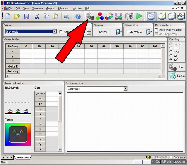
ColorHCFR will now ask you to continuously play a window test pattern with a spacing of 10 IRE from 0 to 100 IRE, while paused at each test pattern to allow the sensor to capture the reading. Start looking for the first test pattern from the Digital Video Essentials: HD Basics test disc, select the disc's menu option "Complete Program Menu" -> "Advanced Video Test Patterns" -> 1080p or 720p -> "Video Black w/ new PLUGE" A test pattern of 0 IRE can be found, and the next test pattern is in the subsequent chapters.
Perform the steps indicated by ColorHCFR while completing all test patterns at the same time, while waiting for ColorHCFR to read the values ​​in each test pattern. Digital Video Essentials: The HD Basics window test pattern is spaced at 5 IRE, so you need to press a chapter twice between each step. The IRE value will be in the test pattern and will be in percentage. For example, 50 IRE is displayed as "amplitude 50%", so it's not easy to make mistakes.
Once completed, you will have a complete set of grayscale data. At 0 IRE, the "no data from sensor" error message may appear in Spyder2. Don't worry, 0 IRE is very dark, so there is usually no way to read the value. However, unless we have information in all the fields, we can't draw the graph. So just press the "Editable Data" check button and enter the 0, 0, 0 to 0 IRE x, y, Y fields. No light output is actually the normal performance of most monitors when outputting 0 IRE, so this is correct. If your light output is quite low at 10 IRE, you may get the same error message, especially if you don't use any equipment to improve your gamma (more on this later). If this happens, temporarily enter the value of the 20 IRE field into the 10 IRE field. Do not enter 0 anywhere except the 0 IRE field. The ColorHCFR software has a minor error that does not allow you to edit the value once you have entered 0.
Step 2.3: Press "File -> Save" in the menu option to save your "pre-correction" grayscale reading. ColorHCFR will save the file as "color.chc". We recommend using a name like "color_before.chc" and let it know that it is the grayscale before your correction.
We used our Barco Cine 8 Onyx CRT projector to set the default settings, including the 6500K color temperature setting, to perform one pass and complete a set of readings. We also turned off the gamma enhancement on our RTC2200 external box to get a more typical reading, as you would see on most monitors. This external box (and other similar products) is used for reinforcing gamma for better shadow detail, most of the displays are more or less in need of such things, especially CRT type monitor. Why do you need its discussion, more information on how it works, and pre-/post-screening, you can see it in this discussion: Gamma correction: What is it? Why do you need it?
Here is the reading we set for the 6500K color temperature projector: 
In the preset 6500K setting, while turning off the gamma reinforcement, what is the performance of this projector? Simply speaking, it is very bad. From 0 to 100 IRE, there is no set of x, y values ​​are near the target point of x=0.313, y=0.329 D65. Because the picture is too dark, we didn't get any reading at 10 IRE. In the above picture, we select the 100 IRE field (reverse white) to see the size of red/green/blue, you can see the histogram in the lower left corner, red is 72%, green is 111%, and blue is 65%. All of them should be close to 100% to be correct, so these colors are clearly completely unbalanced at 100 IRE. If we check other IRE values, we will see that their values ​​are also far away. We get a maximum light output of 10.3 ftL at 100 IRE (we will target a target value between 12-16 ftL later). If the room is a light-controlled room, such as a black wall/ceiling around the curtain, because the brightness perceived by the person is higher, the value is actually not too bad.
Ok, so in the default setting of 6500K, these values ​​are biased and the image is quite poor, but what do these data mean? Most of the information we are interested in can be found in the "Chart s" menu. Let's use the data from our Barco Cine 8 Onyx CRT projector to execute them again, and see what our chart looks like and where they should actually be. Don't make any adjustments on the display first, but take a look at the meaning of these charts and we will adjust them systematically later.
You can select them in the "Chart s" menu and load your own projector chart. If you want to see our Barco Cine 8 Onyx chart, you can download our Barco Cine 8 Onyx ColorHCFR measurements . If you have already installed ColorHCFR, these files can be loaded directly in ColorHCFR. You can load multiple sets of measurements simultaneously in ColorHCFR, so if you like, you can see both sets of graphics at the same time.
All charts in ColorHCFR are interactive and customizable. Pressing the right mouse button on any chart will display additional options. You can also let the mouse stay on the data point and display information about what you are looking at.
Figure 1 - Illuminance (or light output):
The illuminance chart tells us how much light is output at intervals of 10 IRE. This is the Y value and plots its light output as a percentage of the 100 IRE maximum light output and the IRE value (X axis). 
The white dashed line is the target value we want to reach, and the yellow line is the actual value of our projector. You can see that we are consistently below the target value, representing that the image between 0 and 100 IRE is not bright enough. The yellow line is actually the average of red, green, and blue. If you right click on the chart and start the respective red, green, and blue lines, I can see where the problem is. 
As you can see, the red and green are all below the target curve, while the blue just starts to be lower and then becomes too high after about 40 IRE. We want the three colors to completely coincide with the yellow reference line.
In your display, the light output is determined by four controls: Brightness Control, Contrast Control, RGBLowend, and RGBHighEnd. We will use the later steps in this manual to set these four correctly and hope that our curve will match the target line. The light output is also directly related to what is called 'gamma'. The phenomenon of less light output as we see here is because gamma is not correct. We will tell you later how to adjust the gamma.
Figure 2 - Gamma:
Gamma (or more precisely gamma correction) controls the overall brightness of the image or how fast the brightness curve climbs up from the black area. When the gamma value is high, when the brightness increases, the signal climbs out from the black area at a slower speed. Too high an average gamma value will make the image brighter because of the darker black, but will also show less detail in the dark. Our previous illuminance chart is proof. Too low an average gamma value will cause the image to look dull because the dark part is too bright, resulting in a dull image.
Here is our gamma chart from 0 to 100 IRE: 
The average gamma target value our monitor wants to achieve is 2.2. The ColorHCFR software also sets the target value of 2.2. The ideal target value is to match the corrected reference monitor used in the studio. These monitors are designed to have a very flat 2.20 response.
Gamma2.2 gives us a complete balance: enough brightness and perfect dark detail. If your room has only a little light reflection and it is very dark, and you have a very high contrast display (such as a CRT projector), you may find that 2.5 is acceptable (2.2 to 2.5 gamma selection is very good between the calibration staff) Big debate). In most cases, close to 2.2 seems to be better and should be what you try and achieve, remembering that smaller numbers represent more brightness. Later when you measure your grayscale, we recommend trying and setting 2.22. Why it's worth trying, in our CRT projector's light control home theater, we tried 2.5 and 2.2 and prefer a value close to 2.2. If you have a way to adjust the gamma (see below), we recommend that you both try and decide what you like. But you should not exceed 2.5 or lower than 2.2.
Like our example, if the gamma is too high, our overall brightness will be better and we will have a deeper black, but the cost of the dark details will be lost. In our case, we can see from the yellow line that the gamma from 0 to 100 IRE per point is from a fairly high position (3 or more) over the chart, down to 2.27. The average gamma (cyan line) is 2.64 which is quite high compared to 2.2. In the dark, this extra high value means that our settings will completely lose the dark details, which is typical of all CRT monitors. This requires adjusting the gamma control in the display or adding a gamma booster externally to process the signal, as most displays do not have internal adjustment options. (There is no CRT projector with the gamma reinforcement adjustment we want to build).
As mentioned earlier, we use the RTC2200 external box to reinforce gamma to help us reach the appropriate target value. This external box, many high-order multipliers (Lumagen, Crystalio), Moome HDMI cards and converters, X-Vue Box1020, Box1021, Box1040 RGB/Component converters have built-in adjustable gamma reinforcement. If you want the cheapest gamma regenerator, you can use the GammaX adapter. He is made by the designers of the popular HDfury2 HDMI to RGB/Component converter.
Because it is very important to get the appropriate gamma curve, video professional players will look for such gamma reinforcement. Without such equipment in your signal chain, many monitors will not be able to properly conform to the gamma curve, and you will get a blurry and inconspicuous image that lacks shadow detail. More on how gamma reinforcement works, and the screen shots showing why it is needed (especially CRT monitors) can be found in this discussion thread: Gamma Correction: What is it? Why is it needed?
Then we will take the RTC2200 external box back to our signal chain to see what it will make, and explain how and when you should adjust the gamma (if you have this type of adjustment).
If your gamma is greater than 2.2, you should consider adding an adjustable gamma reinforcement to your system.
Figure 3 – Red, blue and green values:
The red, blue and green magnitude chart shows two different things: 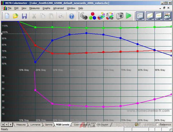
The top half of the chart tells us how far from black (0 IRE) to all white (100 IRE), red/green/blue is 100% from the target value. When the grayscale is perfectly set, all three color lines will coincide at 100%, forming a straight line from left to right. As you can see from our chart, it is far from perfect: green is too high in any section (average about 110%), red is too low in any section (average about 70%), blue Close to perfect from 40-60 IRE, but too low at both ends. This will cause the picture to be too dark in the dark and bright parts, and the part of the middle brightness is too blue-green. Then we will adjust our RGBLowend and RGBHighEnd controls to try to make the three colors flat in the chart.
The bottom half of the chart tells us about DeltaE. DeltaE tells us how far the grayscale is from the target values ​​D65 x=0.313 and y=0.329 at each measurement point from 0 to 100 IRE. It is impossible to achieve an accurate 0.313/0.3290 for each point, so the goal is to keep the DeltaE of each point below 10 as much as possible. DeltaE equals 3 or less is already very close to perfection, and most people can't see this slight imperfection. Our point of departure from the perfect target point D65 is from 23 to over 50. Who said the projector's 6500K is correct?
Figure 4 - Color Temperature:
The color temperature chart is actually a rather useless chart because it simply uses color temperature (one line) to indicate where your points fall, instead of their position relative to the correct D65 point. Higher values ​​(to 9000K) are considered "should" be blue, and lower values ​​(to 3500K) are considered "should" be reddish.
This is our color temperature chart: 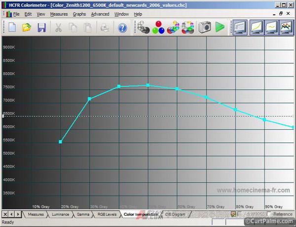
Because it is easier to understand, some magazines like to use this chart. They say that if the chart is completely flat at 6500K from black to white, then the grayscale is perfect, which is not true. You need to understand that there are many points on the CIE chart with a color temperature of 6500K, but only one point is correct: D65 at x=0.313 and y=0.329. You can have a monitor that is a perfect 6500K, but still shows the wrong color. The previous red, blue and green magnitude chart and the next CIE chart will give us the exact image we are actually doing. The less we mention the color temperature chart, the better. Ignore it, it really doesn't work. Don't make the beginner mistake of only posting Don't post your color temperature chart online, causing beginners to make mistakes. There is no other chart or information for reference, it is useless.
Figure 5 – CIE diagram:
We have talked about CIE 1931 before, but let's mention it again. This time it is showing that our point from 0 to 100 IRE is the position that falls on the map. As mentioned earlier, the CIE 1931 diagram shows all the colors that the human eye can see. 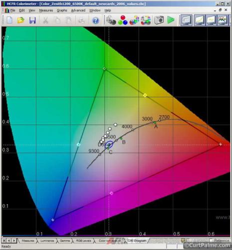
We tried to make all our readings (white circles on the graph) exactly fall on D65 (x=0.313, y=0.329). The D65 doesn't look too much here - it happens to be at the intersection of two white dotted lines. The small blue circle near D65 is the target area where we want our reading to fall. If we can make our white circle fall in the blue circle, our DeltaE will be within 10, which is quite good. That's what we want to achieve at 0 to 100 IRE points. There is a more ugly blue circle near the D65 point on this picture, which represents the better DeltaE 3. If you can achieve it, it will be better! As you can see, our projector presets 6500K. Set a little distance from there.
The figure below is a close-up of DeltaE=10 and DeltaE=3 near the target D65. It also shows that you can move your mouse to get extra money at those points. In this example, we move to our worst-reading IRE 20 reading point, which has a DeltaE of 50.1: 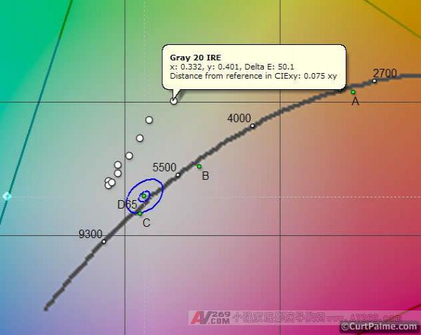
The black triangle on the CIE diagram indicates the color space I selected earlier (HD Rec709 or SD Rec601). This color area is what we want our projector to display. In our case, the color space triangle is the color space of Rec709 (HD), which is slightly larger than the Rec601 (SD) color space (not shown). The three corners of the color space triangle are called 'primary colors' because they represent the three primary colors (solid colors) red, green, and blue, which make up all other colors in the triangle. Then in the manual, we will show you how to measure your primary colors and correspond to your own color triangles to efficiently display the range of colors your display can reproduce. In the ideal situation, the color range of your display should correspond exactly to the SD or HD color range, then the two triangles coincide, but in practice this is unlikely.
It's important to understand that setting your grayscale correctly is not a guarantee that your projector or TV will display 100% correct color. How to properly match the projector or TV display to the colors defined by SD or HD is not only related to the correctness of your grayscale, but also to whether the three primary colors of your display are consistent with the three primary colors defined by SD or HD. This will be explained later in this section.
So now we probably know how bad our grayscale is actually, let us see if we handle this problem!