Electronic crossover preamp section SCM control circuit Figure 6 Figure 7 Follow WeChat Download Audiophile APP Follow the audiophile class related suggestion Friends who love electronic technology may be flipping through some e-books ... 3. Power supply and speaker protection circuit & nb ... Regardless of principle or practice, the advantages of electronic frequency division have been widely recognized ... 
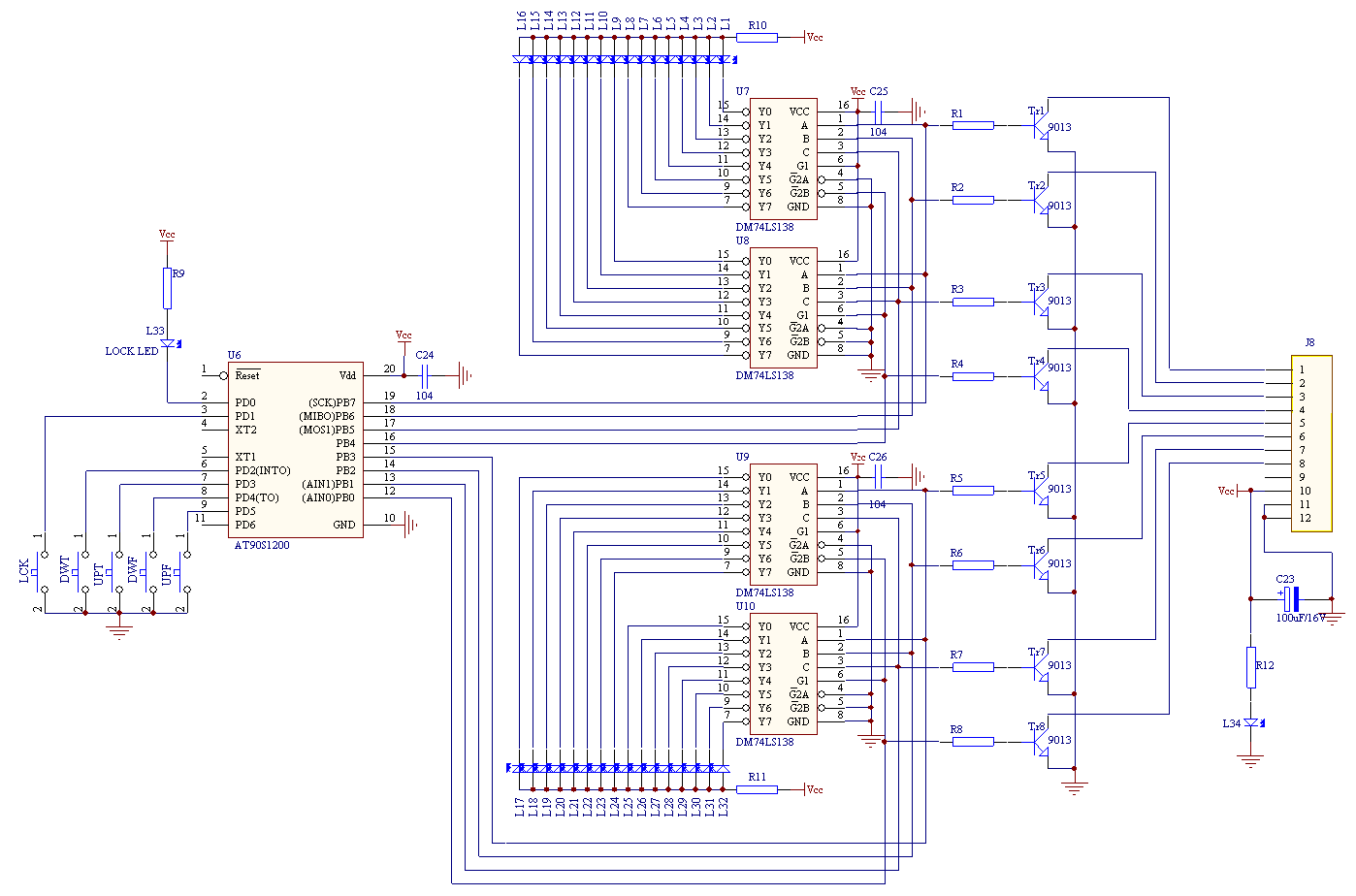
The core of the control circuit is the single-chip AT90S1200. At first, it was a lot of trouble to choose the single chip microcomputer. Due to the limitation of the PCB area, the area of ​​the single-chip microcomputer cannot be too large, and the simpler the peripheral circuit, the better; the crossover frequency adjusted after power off cannot be lost, so there must be E2PROM inside; the I / O port should be sufficient and not too small In order to avoid the use of expansion circuits; we must also be able to use the existing development system to avoid excessive costs ... Finally, this AVR microcontroller was selected after a friend's recommendation. The I / O ports PB0-PB7 of U6 are used to control the 8 control lines of the relay. PD2-PD3 is grounded through two buttons DWT and UPT. It is used to adjust the output on PB4-PB7 for upstream and downstream, and controls the crossover point of the treble ; PD4, PD5 are grounded through two buttons DWF, UPF, used for upstream and downstream control of the output on PB0-PB3, to control the crossover point of the bass. The output of PB0-PB7 is divided into two ways: the first way drives the above 16 relays through the switch tubes Tr1-Tr8; the other way drives 4 * 16 light-emitting tubes through 4 3-8 line decoders 74LS138, respectively displaying high and low bass Crossover point. The button LCK connected to the PD1 port is a keyboard lock. Only when the LCK is pressed for a certain period of time, the indicator LOCK LED goes out, the above-mentioned crossover point adjustment button can adjust the crossover point, used to prevent others from misadjusting. The tweeter is burned at the crossover point. Since this part is just a control circuit, it has nothing to do with the audio signal, so please refer to the relevant books for detailed principles.
4. power supply 
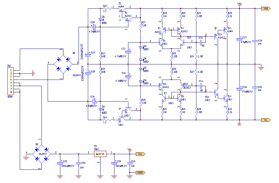
The power supply of this machine is also composed of two parts, which are powered by an R-type 12W transformer with minimal magnetic leakage. The main power supply is a so-called Class A power supply-a parallel regulated linear regulated power supply, which outputs ± 17.5V / 100mA for 4 dual op amps; the other one outputs 5V / 700mA for control circuits and relays. Since they are conventional circuits, they will not be described in detail here.
5. Installation and commissioning 

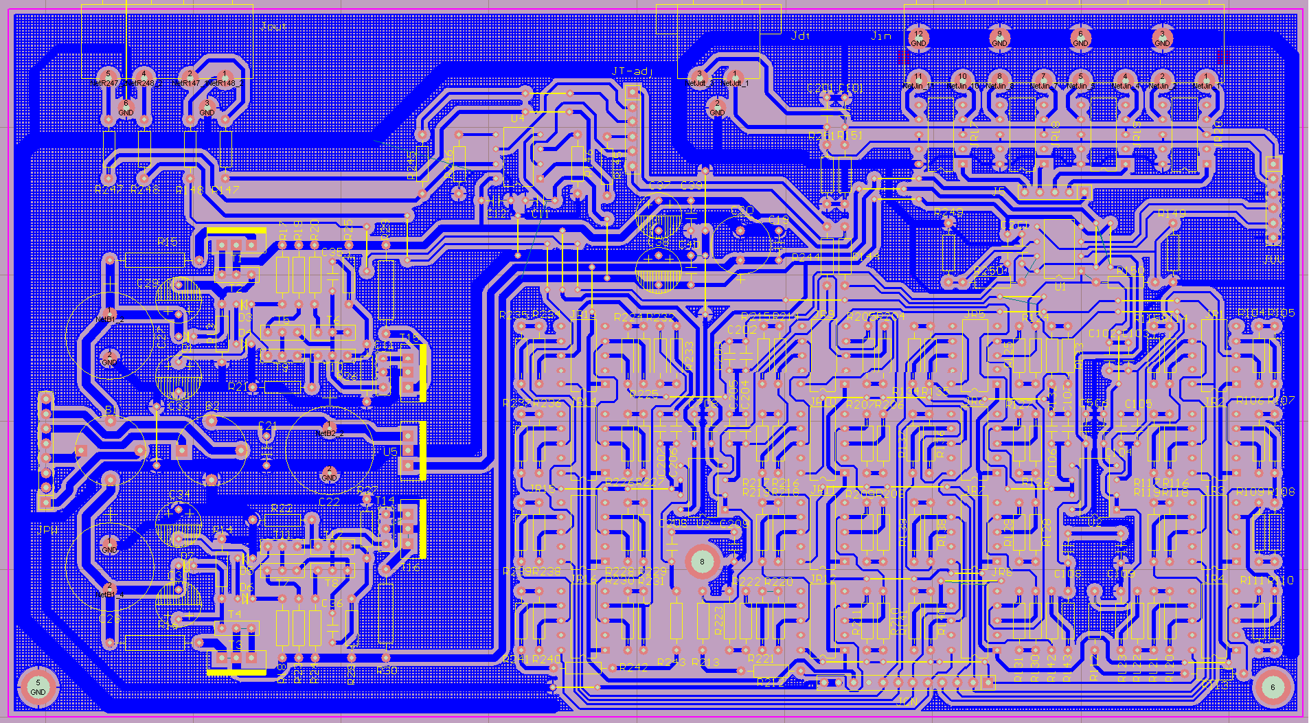
There are two circuit boards in this machine, as shown in Figure 6 and Figure 7. The three parts of Figure 1, Figure 2, and Figure 5 are installed on a circuit board, and the op amp is installed with a gold-plated socket to facilitate the replacement of a better op amp for audiophiles. The control circuit in Figure 4 is installed on the circuit board on the back of the front panel for easy adjustment and use. The two PCBs are connected by a 12-wire flat cable via the interfaces Jcn and Jcd.
If the circuit is connected correctly and the components are good, the entire circuit can work normally without debugging. The only thing that may need to be adjusted is the ± 17.5V power supply. By fine-tuning the size of R26 and R27, the absolute values ​​of the output of the positive and negative power supplies are equal, and the error should not exceed 0.1V. 


![[Photo] Electronic constant current source](http://i.bosscdn.com/blog/20/06/41/523130482.gif)
![[Photo] Part 1 of electronic preamplifier](http://i.bosscdn.com/blog/20/06/41/513834375.gif)
![[Photos] The post-stage part of the electronic frequency divider before and after the amplifier (2)](http://i.bosscdn.com/blog/20/06/41/513441701.gif)
![[Photo] The pre-stage part of the electronic frequency divider front and rear stage amplifier (1)](http://i.bosscdn.com/blog/20/06/41/513435471.gif)
Interesting and informative information and technical dry goods
Create your own personal electronic circle
Lock the latest course activities and technical live broadcast
comment
Publish
[Photo] Electronic constant current source
Posted at 2006-04-15 23:01 • 214 times read
[Photo] Part 1 of electronic preamplifier
Posted at 2006-04-15 13:08 • 1067 views
[Photos] The post-stage part of the electronic frequency divider before and after the amplifier (2)
Posted at 2006-04-15 13:04 • 641 views
[Photo] The pre-stage part of the electronic frequency divider front and rear stage amplifier (1)
Published on 2006-04-15 13:04 • 1126 times read