3. Power supply and speaker protection circuit Picture 11 Picture 12 Figure 13 Figure 14 overall effect: Follow WeChat Download Audiophile APP Follow the audiophile class related suggestion Friends who love electronic technology may be flipping through some e-books ... Regardless of principle or practice, the advantages of electronic frequency division have been widely recognized ... 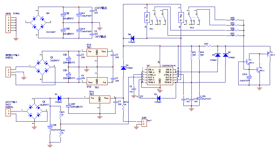
The power supply and protection circuit are shown in Figure 11, and the PCB is shown in Figure 12. The main power rectifier bridge is directly fixed on the heat sink, so there is no installation location on the PCB. The ± 15V output is implemented by 7815 and 7915. The protection circuit consists of a LM556N and its peripheral circuits. In the figure, T1, T2 and T3 constitute the midpoint potential detection circuit; half of 556 and RP4 and CE9 constitute the power-on delay circuit; the other half of 556 and D1, RP1 and RP2 and CE8 constitute the quick-off circuit of the shutdown speaker ; Two relays KL1, KL2 control the connection and disconnection of high and low speakers. The whole machine is powered by a 500VA toroidal transformer: main power supply 28V + 28V / 8.4A, auxiliary power supply 16V + 16V + 16V / 0.5A. The capacity of the horn protection relay is 2 * 8A / 250V, 12V drive. 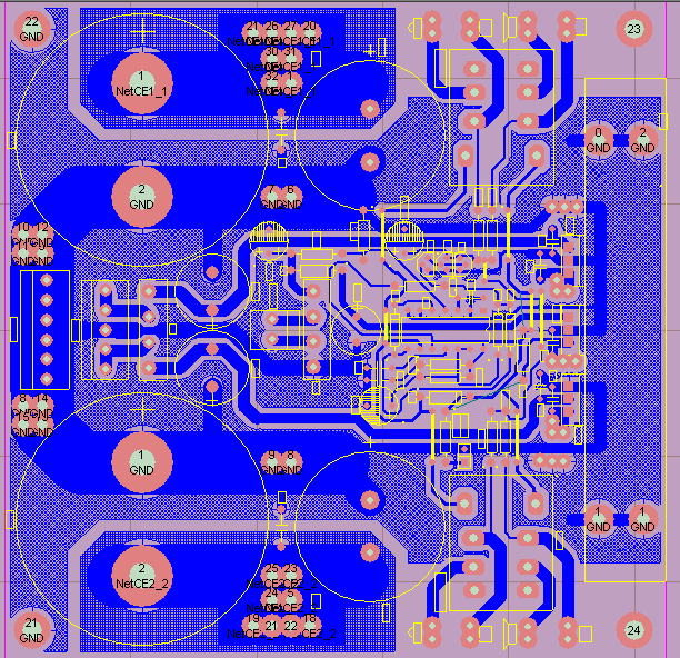
4. Input and control circuits 
The input circuit principle is shown in Figure 13, and the PCB is shown in Figure 14. In the picture, Jin is a 2 * 2 RCA signal input socket, and the high and low frequency signals of the left and right channels after the previous frequency division are input, and Jout is the plug row connected to the power amplifier board, which outputs high and low frequencies to the left and right channel amplifier boards respectively Signal; JFO is used to directly output the low frequency signals of the left and right channels, which is prepared for the external subwoofer. Jcn is the working mode selection output interface, among which pins 1-4 are used to connect the relay control interface JP1 or JP2 in Fig. 8, one is connected to each power amplifier board; pins 5-7 are used for the working mode indicator on the control panel, When SW is connected to a different gear, the corresponding LED is lit. Jvp is a 12V control power interface. 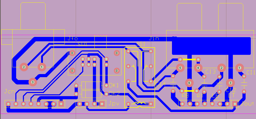
The following mainly explains the purpose of the working mode switch SW. There are three working modes of this machine, which are all set by SW, and provide multiple usages for the amplifier, which are explained separately below.
The first mode: standard pre-frequency division mode (4in / 4out). When the 1-2 end of SW is closed, the relay JS1 is released. At this time, if Jin inputs 4 audio signals, it will directly output from Jout to the power amplifier board through 4 DC blocking capacitors (which may be omitted), and the DC voltage of 12V passes through DK1 Output to pins 1 and 4 of Jcn, through JP1 or JP2 to control the relay K1 and K2 on the power amplifier board, the high and low power amplifier circuits are normally working in the frequency division state.
The second mode: dual amplifier power frequency division mode (2in / 4out). When the 1-3 terminals of SW are closed, JS1 pulls in. If only the full-band signals of the left and right channels are input from the low-frequency input terminal of Jin, the signal is also output to the output terminal of the treble signal of Jout at the same time, 12V power supply It is also output to pins 1 and 4 of Jcn through DK2. The four amplifiers on the power amplifier board are working in the full-band state and can be used for power division in the "dual amplifier" mode.
The third mode: two-channel mode (2in / 2out). When the 1-4 end of SW is closed, JS1 is released. If at this time, as in the second mode, only the full-band signals of the left and right channels are input from the low-frequency input terminal of Jin, the tweeter will have no signal input. Since there is no 12V control voltage output on pins 1 and 4 of Jcn at this time, K1 and K2 are released, and the tweeters of the left and right channels stop working because the ± 15V power supply is cut off, and they do not consume power. At this time, the entire amplifier is a standard Hi-Fi stereo amplifier.
5. For assembly and debugging, except for the ones marked in the circuit diagram, the resistors are all 1 / 4W metal film resistors. For small-capacity capacitors, use CBB capacitors. The matching error of the power tube is not high, and it can be used when the matching error of 0.5A is less than 20%. Note that LM1875T should be installed with a heat sink with a heat dissipation area of ​​not less than 30cm2. The debugging of the whole machine is very simple, and only the quiescent current and midpoint potential need to be debugged. By adjusting the two multi-turn potentiometers of each power amplifier on the board multiple times, the quiescent current can be adjusted to a predetermined value, and the midpoint potential of the output terminal can be adjusted to below 50mV. The method is the same as other power amplifiers. It should be noted that: first of all, the multi-turn potentiometer should be adjusted to the position with the largest resistance, the ± 15V power supply is normal, and the power tube is installed on the heat sink. If the quiescent current is relatively large, you can increase it by 5-10% during the adjustment. After the heat is balanced, the current will automatically decrease to the set value. For tweeters, the quiescent current should not exceed 0.8A, and each pair of tubes in the bass amplifier should not exceed 0.5A. The best quiescent current after the test is: 0.5A in the treble power amplifier part and 1.0A in the bass part. At this time, the sense of hearing and power consumption reach a relatively good balance. For 2SK1058 / J162, it is difficult to hear the difference by adding quiescent current to each tube. In fact, the quiescent current of each pair of tubes changes from 0.2A to 0.5A, and the difference in hearing sense is very small.
After actual measurement, the gain of this machine is about 23dB (15 times), with a suitable heat sink, by adjusting the quiescent current can work in Class A, A and B. Maximum output power: 2 * 80W for bass and 2 * 35W for treble. When the output power of each channel is 10W, the full-band distortion is less than 0.5%, and the signal-to-noise ratio is> 85dB.
There are two sets of 2 * 8 output terminals at the output of the machine, which can be connected to two pairs of speakers at the same time, and switched by the A / B switch on the left side of the panel. Since the treble signal has been inverted in the pre-frequency division stage, it cannot be connected in reverse when the tweeter is connected. 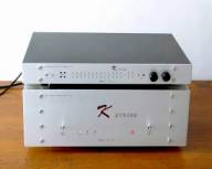


![[Photo] Electronic constant current source](http://i.bosscdn.com/blog/20/06/41/523130482.gif)
![[Photo] Electronic frequency division preamp section](http://i.bosscdn.com/blog/20/06/41/513841338.gif)
![[Photo] Part 1 of electronic preamplifier](http://i.bosscdn.com/blog/20/06/41/513834375.gif)
![[Photo] The pre-stage part of the electronic frequency divider front and rear stage amplifier (1)](http://i.bosscdn.com/blog/20/06/41/513435471.gif)
Interesting and informative information and technical dry goods
Create your own personal electronic circle
Lock the latest course activities and technical live broadcast
comment
Publish
[Photo] Electronic constant current source
Posted at 2006-04-15 23:01 • 214 times read
[Photo] Electronic frequency division preamp section
Posted at 2006-04-15 13:08 • 715 views
[Photo] Part 1 of electronic preamplifier
Posted at 2006-04-15 13:08 • 1067 views
[Photo] The pre-stage part of the electronic frequency divider front and rear stage amplifier (1)
Published on 2006-04-15 13:04 • 1126 times read
