A power synthesizer uses multiple high-frequency transistors to add the high-frequency power generated by them to a common load. Figure 3-12 is a block diagram of a commonly used power synthesizer. The principle of the power synthesis circuit is to use N identical power amplifiers, and the output power of the hybrid circuit is superimposed on the common load, that is, the total output power P L = NP 1 At the output of the transistor, when the two tubes work normally, the two tubes output the same voltage, but because the current on the load is doubled, the power obtained on the load is the sum of the output power of the two tubes, that is The requirement for the power synthesizer is 1 If the output amplitude of each amplifier is equal and the rated power supplied to the matched load is P1, then the total power of the N amplifiers on the load should be NP1 When U A = 0, because the current value flowing through the load is reduced from the original half, the power is reduced to 1/4, and the other half of the power output by the A tube is consumed by the balancing resistance RT, as shown in Figure 3-36. It is the principle circuit of the inverting power synthesizer. The input and output terminals also have -3dB couplers for distribution and combination circuits. Figure 3-37 is the actual circuit of the reverse phase power synthesizer. It works at 1.5 ~ 18MHz and the output power is 100W. Follow WeChat Download Audiophile APP Follow the audiophile class related suggestion The input board is a small PCB m ... 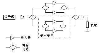
Figure 3-12 Power synthesizer composition
High-power tube: tens of kilowatts-hundreds of kilowatts High-power transistor: several watts-tens of watts Known by the principle of the 3dB coupler, when the input resistance of the two transistors is equal, the input voltage of the two tubes is equal to the input voltage of the coupler  …………………………… [3-15]
 ![]()
2 The input terminals of the synthesizer should be isolated from each other. When any one of the power amplifiers is damaged or fails, it will not affect the working status of other amplifiers.
3 When one or several amplifiers are damaged, the power drop on the load is required to be as small as possible.
4Meet the requirements of broadband operation. Within a certain passband range, the power output should be stable, and the amplitude and phase changes should not be too large, while ensuring the impedance matching requirements. 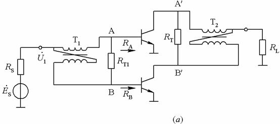
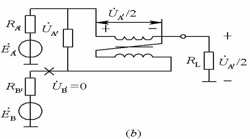
Figure 3-35 In-phase power combiner (a) AC equivalent circuit (b) Open circuit of signal source makes the equivalent circuit 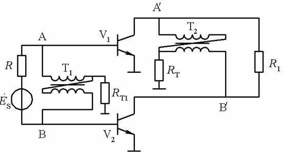
Figure 3-36 is the principle circuit of the inverting power synthesizer 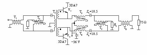
Figure 3-37 is the actual circuit of the reverse phase power synthesizer 


![[Photo] Power Meter & Frequency Meter Production (English)](http://i.bosscdn.com/blog/20/06/41/5203749667.gif)
Interesting and informative information and technical dry goods
Create your own personal electronic circle
Lock the latest course activities and technical live broadcast
comment
Publish
[Photo] Design and production of power stabilized inverter power supply
Posted at 2006-04-16 23:10 • 662 views
[Photo] Power Meter & Frequency Meter Production (English)
Posted at 2006-04-15 20:38 • 610 views