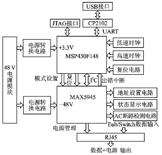
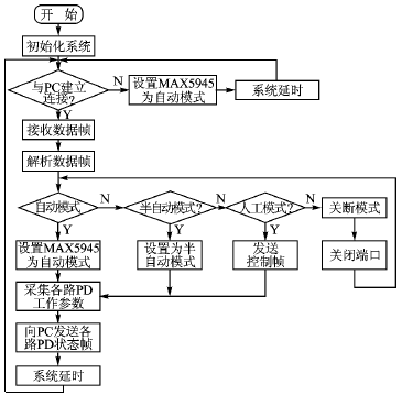
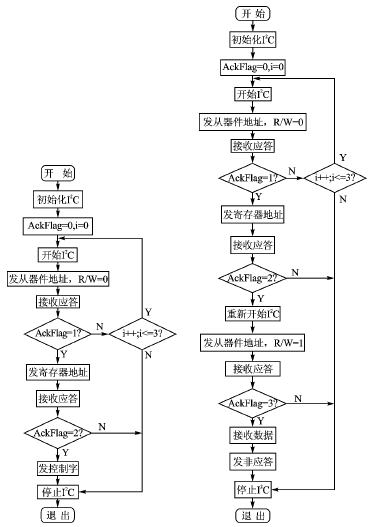
Power-over-Ethernet equipment using MAX5945 Network power supply is one of EPA's key technologies. This article briefly introduces the IEEE802.3af standard. The system analyzes the functional requirements and overall design of the Ethernet power supply equipment. The MSP430F148 microcontroller and the MAX5945 Ethernet power supply power manager are selected. Based on the I2-CBUS communication specification, an Ethernet conforming to the IEEE802.3af standard is developed. Network power supply equipment, and gives the application examples of the power supply equipment in the EPA system. Keywords IEEE802.3af PoE Power over Ethernet equipment MSP430F148 MAX5945 I2C-BUS EPA MSP430F148 is a Flash MCU in the MSP430 series of ultra-low power mixed-signal controllers launched by the American company TI. It has a 16-bit RISC structure. The 16 registers and constant generators in the CPU enable the MSP430 microcontroller to achieve the highest code efficiency; the flexible clock source allows the device to achieve the lowest power consumption; the digitally controlled oscillator (DCO) Can make the device wake up quickly from low power consumption mode, activate to the active working mode within 6μs. It is applied to the power supply equipment of Ethernet, which can conveniently realize the control of the power supply management chip of the power supply of Ethernet, and can also make the user conveniently monitor the power supply equipment of the Ethernet through the terminal monitoring program. 1 Introduction to IEEE802.3af standard [1-3] The IEEE802.3af standard defines a method that allows 48 V DC power to be transmitted while transmitting data over Ethernet. It introduces Power over Ethernet (PoE) technology into the existing network infrastructure and is compatible with the original network equipment; it can provide a maximum of 12.95 W of power with a transmission distance of 100 m. PoE consists of two parts: Power Sourcing Equipment (PSE) and Powered Device (PD). The PSE is responsible for injecting power into the Ethernet cable and implementing power planning and management. The IEEE802.3af standard defines two types of PSE, one is "Endpoint PSE" and the other is "Midspan PSE". Endpoint PSE is an Ethernet switch, router, hub, or other network device that supports PoE. This device transmits power on the signal pair or spare pair of the CAT5 cable; Midspan PSE is a device specifically designed for power management. Data exchange, it usually works together with data exchange equipment to realize the function of power over Ethernet. The main working steps of PSE are: ①Discovery. Before allowing the PSE to supply power to a legal PD, it must use a limited power test source to check the characteristic resistance. The two-point detection method is generally used to complete the detection work. The PD is responsible for separating the 48V power supply and data signal from the network terminal equipment, and transforming the 48V DC power supply into the 5V DC required by the terminal equipment for normal operation. When the PSE detects and classifies the PD, the PD should respond accordingly; meanwhile, during the PSE power supply process, the PD sends a continuous working signal through the Maintain Power Signature (MPS). 2 Hardware architecture and composition [46] In the PoE system, PSE is the main part. In addition to the above power management functions, the PSE must be able to provide real-time operating parameters for each PD in some special applications, and can monitor the entire system through the terminal monitoring program running on the PC. The PSE system is divided into hardware and software. Figure 1 shows the hardware architecture of the power supply system. The system is mainly composed of power module, power conversion circuit, MAX5945 and its peripheral circuits, MSP430F148 and its peripheral circuits, CP2102 and its peripheral circuits. The 16-bit MSP430F148 reads and writes to the MAX5945 through I2CBUS to realize the power management function; sets the working mode of the MAX5945 through the mode setting signal line; obtains the error interrupt signal from the MAX5945 through the error interrupt signal line, thereby resetting the MAX5945 through the reset signal line Generate an effective low-level reset pulse signal. At the same time, the MSP430F148 communicates with the terminal monitoring program on the PC through the internal UART module and the CP2102 bridged to the USB interface; it can also communicate with the PC through the serial port, the system monitors intuitively, and when the system recognizes that it has not been established with the PC It will run autonomously when connected. The following describes the specific functions of each part of the system hardware. 2.1 Power supply The power supply part mainly provides working voltage for each device in the system. When the system works, three voltages of 48 V, +5 V and +3.3 V are required. The +5 V required by the CP2102 is provided by the USB interface of the PC, and the other devices are output by the power module. +48 V or provide working voltage after conversion. Power supply module: 220 V to -48 V switching power supply module. Since one MAX5945 can manage the power supply of four Ethernet ports, multiple MAX5945 can be mounted on I2CBUS, so the power of the power module can be selected according to the actual situation . The MAX5945 only needs an external -48 V power supply for operation, which is provided by the power module after the inversion of the conversion circuit. Power conversion circuit: The working voltage of MSP430F148 is +3.3 V. This design uses a power conversion chip LM2575HVS5.0 to convert +48 V to +5 V. After AMS11173.3, it converts +5 V to MSP430F148. V. 2.2 Power over Ethernet manager section MAX5945 is a four-way network power controller introduced by Maxim Corporation for power supply equipment (PSE) compatible with IEEE802.3af. The device provides PD detection, classification, current limiting, and DC and AC load disconnection detection. The MAX5945 can be used in terminal PSE (LAN switch / router) or mid-span PSE (power injection) systems. The MAX5945 can work independently or can be controlled by software through an I2C compatible interface. Separate input and output data lines (SDAIN and SDAOUT) allow the use of optocouplers. The INT output and 4 shutdown inputs (SHD_) allow quick response from error occurrence to port shutdown. The RESET input allows the hardware to reset the device. The MAX5945 is completely configured and programmed by software. Hierarchical overcurrent detection enables the system power management to detect whether the current drawn by the PD is greater than the current allowed by its classification. MAX5945 has 4 working modes, namely automatic mode, semi-automatic mode, manual mode and shutdown mode. In automatic mode, the functions of standard PD detection, classification, and power supply are automatically realized without the need for microcontroller control. Therefore, in a low-cost design, you can directly set MAX5945 to automatic mode (in this mode, MAX5945 uses DC disconnect The detection method detects whether the PD is disconnected). In semi-automatic mode, the MAX5945 repeatedly performs line detection and / or grading as needed, regardless of the connection status of the port. Use software commands to turn off power to the port each time. In manual mode, superior AC disconnection detection can be performed, and the voltage and current of each PD can be obtained in real time. These need to be controlled by the I2C bus to control the read and write registers inside the MAX5945. To complete the advanced management of power supply. Shutdown mode terminates all activities and safely powers off the port. The switch between automatic, semi-automatic, and manual modes does not work until the device completes its current task. When the port is set to shutdown mode, the port immediately stops all work and maintains an idle state until it exits shutdown mode. Address setting circuit: MAX5945 is a slave device, 4 address lines can choose 16 different I2C addresses for MAX5945. AC disconnection detection circuit: In PMM mode, the AC5 disconnection detection signal superimposed in the power supply loop can be generated by setting the internal register of the MAX5945 in conjunction with an external AC disconnection detection circuit. Status display circuit: MAX5945 needs to add a detection display circuit to the power supply loop of each port. In this way, the MAX5945 can intuitively display the working status of each port in all three modes. 2.3 SCM control part MSP430F148 is a Flash type single-chip microcomputer in the MSP430 series of ultra-low power mixed-signal controllers launched by TI Company. It uses a reduced instruction set to operate all functional modules. It has a 16-bit RISC structure, with 48 KB Flash, 2 KB RAM, USART and other modules on-chip; the 16 registers and constant generator in the CPU enable the MSP430 microcontroller to achieve the highest code efficiency; by using different clock sources Can make MSP430F148 meet different low power requirements; digitally controlled oscillator (DCO) can make MSP430F148 switch from low power mode to active working mode within 6μs; support online simulation function, development tools can support C well Language development can improve the efficiency of software development. The safety fuse of MSP430F148 can protect the code of the program. The MSP430 F148 microcontroller uses a memory-memory structure, that is, a common space is used to address all functional modules, and a reduced instruction set is used to operate all functional modules. Its internal structure includes CPU, memory, oscillator and clock generator and peripheral modules. Clock circuit: The clock module of MSP430F148 is mainly composed of high-speed clock, low-speed clock and digitally controlled oscillator. The digitally controlled oscillator is integrated inside, and the high-speed clock of 8 MHz and the low-speed clock of 32.768 kHz are generated by an external clock circuit. Reset circuit: A resistor-capacitor reset circuit is used to manually reset the MSP430F148 externally. JATG interface: The MSP430F148 microcontroller is embedded with a JTAG interface and supports the boundary scan technology standard IEEE1149.1. It is mainly composed of 5 control signals TCK, TDO, TDI, TMS and RST. Through the integrated IDE development environment, it can be easily debugged online Code. Buzzer: When the program detects an error in MAX5945 operation, it sends a pulse signal of a certain frequency to the buzzer through the P3.3 port of MSP430F148, which can play the role of sound alarm. 2.4 USB Bridge CP2102 CP2102 is a highly integrated dedicated communication chip. The function of the chip is to realize the data conversion between UART and USB format. It integrates a full-speed function controller, EEPROM, buffer and UART data bus with modem interface signals that comply with the USB2.0 standard. It also has an integrated internal Clock and USB transceiver. Through CP2102, the bridge between UART and USB can be easily realized, thereby adding a USB communication interface to the system. 3 software design and implementation [68] The software implementation of PSE mainly includes two parts: PSE running control program running on MSP430F148 and PSE terminal monitoring program running on PC. The two communicate through the USB interface formed by CP2102. 3.1 PSE operation control program The PSE operation control program mainly implements functions such as system initialization, control of the MAX5945, communication with the PC, and packaging and analysis of data. As shown in Figure 2, when not connected to a PC, the MAX5945 is set to work in AM mode, and the MAX5945 will operate autonomously; at this time, the specific operating data of each power supply port cannot be obtained, and each port can only be displayed through the LED in the status display circuit Running status. When connected to a PC, the system will set the MAX5945 to the corresponding working mode according to the user's requirements. At this time, the system can collect the operating parameters of each port. In the SAM and PMM modes, the system will be able to partially or completely Control the power supply of each port. The monitoring process is achieved by reading and writing the MAX5945 port registers. 3.1.1 System initialization System clock initialization: select 8 MHz clock XT2 as the clock source of the main clock, and select DCO as the clock source of the subclock I / O port initialization: Set P3.3 as the output to drive the buzzer; P4.0 is set to the output as the mode selection signal of MAX5945; P4.2 is set to the output as the reset signal of MAX5945; P4 .1 is set as an input, as the MAX5945 error interrupt input signal. Serial port initialization: MSP430F148 communicates with CP2102 through UART1. UART1 is set as follows: the number of transmitted characters is 8; the transmission / reception rate is 9 600 bps; the auxiliary clock ACLK is selected as the clock source of the baud rate generator; the serial port reception and transmission operations are enabled; P3.6 and P3. 7 The function selection register is set to serial port transceiver mode. 3.1.2 Implementation of I2C-BUS There is no standard I2C-BUS communication module in MSP430F148, therefore, the SDA and SCL in the I2C-BUS communication specification need to be simulated by software through P3.0 and P3.2 to complete the I2C-BUS read and write operations. (1) I2C-BUS write operation The I2C-BUS write function "void WriteI2C (char Addr, char Reg, char Ctr)" is composed of the address of the formal parameter Addr? MAX5945, the address of the Reg? MAX5945 register, and the control information of Ctr ?; ), I2CSent (unsigned char data), I2CReceiveAck (), I2CReceiveAck (), I2CReceiveAck (), I2CStop () and delay () subfunctions. The I2C-BUS write function is used to write control information to the specified MAX5945 internal register. The specific I2C-BUS write operation flow is shown in Figure 3. (2) I2C-BUS read operation The I2C-BUS read function "void ReadI2C (unsigned char Adr, unsigned char Rg)" consists of the address of the formal parameter Adr? MAX5945 and the address of the register Rg? MAX5945. The result of this operation is to read the information in the Rg status register in the MAX5945 with address Adr and store it in a char-type global variable. The read function is composed of I2CInit (), I2CStart (), I2CSent (), I2CReceiveAck (), I2CSent (unsigned char data), Rec_dat (), I2CSentNAck (), I2CReceiveAck (), I2CStop () and delay () subfunctions These subfunctions work together to complete the I2C-BUS read sequence. The specific I2C-BUS read operation flow is shown in Figure 4. 3.2 PSE terminal monitoring program The PSE terminal monitoring program mainly realizes the real-time monitoring function of each power supply port. Since the USB bridge chip CP2102 is used, the monitoring program can logically complete the serial communication. Various control data is set through the terminal monitoring program, and the real-time working parameters of each power supply port collected at the same time will also be visually displayed on the monitoring program. The terminal monitoring program implements advanced management functions for power supply. 4 Conclusion With the maturity and development of Power over Ethernet technology, Power over Ethernet technology will gradually be widely adopted. This design uses the MSP430F148 microcontroller and the Power over Ethernet Manager MAX5945 to develop a monitorable advanced Power over Ethernet management system that complies with the IEEE 802.3af power over Ethernet standard. The system can also be simplified according to actual needs to reduce costs. This system has been applied in the EPA (Industrial Automation Ethernet) system and has a good use effect.
Interface Module,now we have connector module series, Relay Module series, miniature relay module series and soled state relay module series.There are many advantages, for example, the circuit board is fixed to prevent poor contact caused by vibration, to protect the circuit board from damage, to install the circuit board on the guide rail and so on.
Interface Module Interface Module,Network Interface Module,Ethernet Interface Module,Communication Interface Module Suzhou WeBest Electronics Technology Co.Ltd , https://www.webestet.com
â‘¡ Classify. After detecting a valid PD, the PSE uses a detection voltage of 15.5 ~ 20.5 V to detect the PD power level. The PD indicates to the PSE the maximum power it needs by absorbing different constant currents (graded characteristic signals) from the line.
â‘¢ Delivery (delivery). After successful detection and classification, the PSE normally supplies power to the PD. During power supply, the PSE also monitors the power supply of each port to provide undervoltage and overcurrent protection.
â‘£ Shutdown. When the PD is disconnected, the PSE stops supplying power to the line. The PSE can use the DC disconnection detection method or the AC disconnection detection method to detect whether the PD is disconnected. 
Figure 1 Hardware architecture diagram of Ethernet power supply equipment 
Figure 2 PSE operation control flow chart 
Figure 3 I2C-BUS write operation flow chart 4 I2C-BUS read operation flow