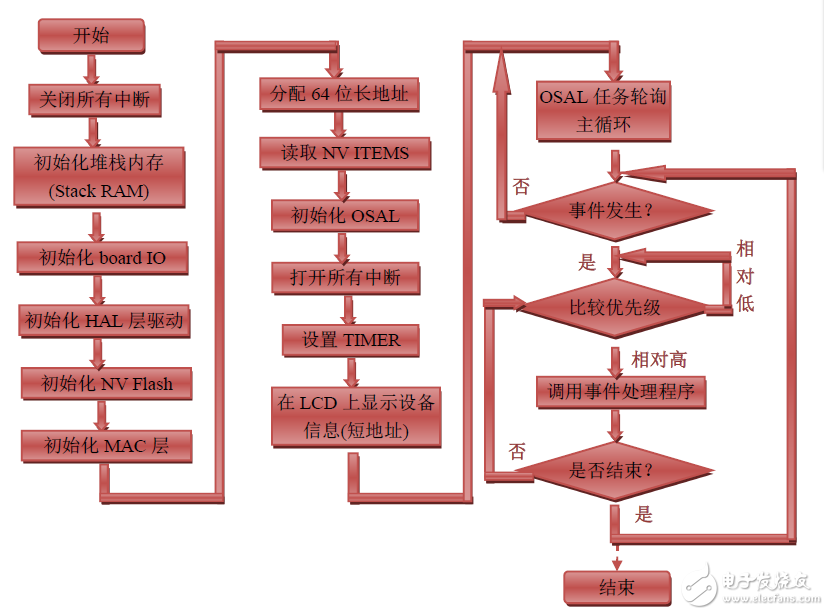
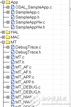
I. Introduction Starting today, we have to officially start the zigbee-related communication experiment. The protocol stack I use is ZStack, which is TI ZStack-CC2530-2.3.0-1.4.0. You can also download TI directly from TI's official website. The company's protocol stack code for cc2530, after all, as a beginner, we should not go deep into the protocol stack is written in code, after all, zigbee is quite mature, we should first learn to use the zigbee protocol stack for communication, and can Applied to practical projects, such as smart furniture, I don't know if everyone feels the same, so let me introduce you to the principle and architecture of zigbee communication. 2. ZStack architecture ZStack's architecture consists of modules called layers. Each layer provides a specific service to its upper layer: that is, the data transmission service is provided by the data service entity; the management entity provides all other management services. Each service entity provides an interface to its upper layer through a corresponding Service Access Point (SAP), and each service access point performs the corresponding function through a service primitive. ZStack is divided into physical layer, medium access control layer, network layer, and application layer according to IEEE 802.15.4 and ZigBee standards. The physical layer provides the basic services, data transmission and reception, and the network layer provides the services that each node connects. It is the key to zigbee network communication. The application layer is the focus of our attention, providing the application framework and ZDO. If you want to understand the specific content of the architecture, you can read the documentation yourself. Let me introduce you to how zigbee works. ZStack is built using the idea of ​​an operating system, uses an event round-robin mechanism, and has a dedicated Timer2 for timing. Starting from the work of CC2530, Timer2 is timed again and again, with acquisition, transmission, reception, The main workflow of the entire ZStack, as shown in the figure, is roughly divided into the following 6 steps: This is the general process of zigbee processing tasks. Code analysis The code of the protocol stack is many and complex, and the above figure will understand. . . This is only a part, so we don't have to focus too much on the preparation of the protocol stack, but we must learn how to use it. The main thing we learn and configure is the SampleApp.c file in the figure. It is mainly applied to the application. For different applications, just modify it and the underlying configuration file. It has six very important functions, these six functions, which are about initializing user functions; there are processing about all events; there are key service functions written; there is processing for receiving data; there is a data sending function of. Let's analyze these six functions: Void SampleApp_Init( uint8 task_id ) This is a function that the user uses to initialize the task. It is called during the system initialization phase. Moreover, when it is called, it should have the corresponding task initialized (that is, what initialization the user has, In this function), such as: hardware initialization, data table initialization, power initialization, and so on. Uint16 SampleApp_ProcessEvent( uint8 task_id, uint16 events ) This is an event handler (all events are managed by it). When a registered event occurs, it is called by the main function to handle the event, including timers, messages, and user-defined events. and many more. Void SampleApp_HandleKeys( uint8 shift, uint8 keys ) This function is called for SampleApp_ProcessEvent( uint8 task_id, uint16 events ): When the button is pressed, the case KEY_CHANGE in the SampleApp_ProcessEvent function is executed. The service function of this case is SampleApp_HandleKeys( uint8 shift, uint8 keys ), we can Add a button to determine the function, determine which button, and then perform related tasks. Void SampleApp_MessageMSGCB( afIncomingMSGPacket_t *pkt ) This function manages all received data. As for which device the data came from, it is resolved based on the cluster ID. Void SampleApp_SendPeriodicMessage( void ) This function is a periodic data sending function, which is called when the device is set to broadcast periodically. It is where we set the sending data. Void SampleApp_SendFlashMessage( uint16 flashTime ) This function is a service function of the void SampleApp_HandleKeys( uint8 shift, uint8 keys ) function. We rarely use this function, so we will not explain it in detail. The above are the six commonly used functions. For beginners, it is enough to use the zigbee protocol. First, the driver is transplanted, and the hardware is initialized. After modifying these 6 functions, the zigbee can be easily applied. I wrote it here today. I don’t post the protocol stack code too much. I need friends to contact me and learn from each other. This is just my experience.
APM 360V switching power supply could
be widely used for charging 48V battery system. You can quickly and easily
operate the power supply with its rotary knobs and buttons. Besides, free
monitoring software for you to remote control. External control is also
supported.
This 360V series also covers 48 volt
power supply .At present, battery widely adopts 3-stage charging
algorithm, the DC Power Supply supports switch over between CC
mode and CV mode, which can be set flexibly according to the display of the
power supply`s voltage to choose to enter quick charge phase, equalized charge
phase or floating charge phase.
Some features of the power supply as below:
360V DC Power Supply,AC DC Variable Power Supply,Bench Power Supply,Desktop Power Supply APM Technologies Ltd , https://www.apmpowersupply.com
Execute when tasks such as display... are executed. After each layer is initialized, the system enters a low-power mode. When an event occurs, the system wakes up, begins to enter an interrupt processing event, and continues to enter a low-power mode after the end. If several events occur at the same time, the priority is judged and the events are processed one by one. This software architecture can greatly degrade the power consumption of the system. 
(1) Close all interrupts;
(2) Initialization of the chip (onboard peripheral);
(3) Internal initialization of the chip;
(4) Initialize the operating system;
(5) Turn on all interrupts;
(6) Execute the operating system. 
The functions of this function include: button processing, data reception, and data transmission. Of course, users can add other events themselves, and we add our own serial events in this function.
Inside the function is a switch statement, the key is the case and the service function behind it. Users can define different cluster IDs (in SampleApp.h) according to different functions, then add a case named after the cluster ID in this switch statement, and write their own application in the case.