I. Method of detecting fatigue level Driver fatigue driving is an important factor in causing traffic accidents. The National Highway Traffic Safety Administration (NHTSA) survey in recent years [1] shows that an average of 56,000 accidents per year are related to fatigue driving, resulting in 40,000 injuries and 1,544 deaths (3.7% of total traffic accident deaths). It also shows that 27% of respondents indicated that they have experienced driving and dozing. According to the statistics of the Traffic Management Bureau of the Ministry of Public Security in 1999 and 2000, the traffic accidents caused by driving fatigue accounted for only 1.4% and 1.15%; the resulting death rates were 2.5% and 2.23% respectively; but negligence, judgment errors, measures The three items were improperly added, which were 18.8% and 20.29%, respectively. The resulting mortality rates were 18.6% and 20.84%. The driving causes of these three accidents may be mixed with driving fatigue. Therefore, it is necessary to develop an alarm device capable of determining the degree of fatigue of the driver. Many countries are now actively conducting research in this area. Some French research institutes have teamed up to develop a system to monitor driver's loss of attention, which can alert drivers through sound or light signals. The French company Toulouse Siemens VDO, which is responsible for the development of this technology, hopes to install the device in the car in 2006. This research work was launched last year with a total investment of 17 million francs, mainly to study the feasibility of installing this device on the car. At present, there are many methods for detecting the physiological characteristics of driver fatigue, which can be divided into two types: contact detection and non-contact detection. The main ones are as follows: This article refers to the address: http:// Principle of the PERCLOS method PERCLOS refers to the proportion of time taken when the eye is closed within a certain period of time. In the specific test, there are three measurement methods: p70, p80, and em. III. Design of image acquisition system Firstly, considering the driving environment of the driver, the detection system must work normally at night or under weak light, so it is necessary to use a camera system with its own light source. This system uses the infrared LED comes with an infrared camera to capture images not only ensure adequate lighting and invisible infrared light, it does not affect the driver's driving. To reduce the interference of the external environment, reducing the complexity of the image processing, the filter should be as background image. Image acquisition system selects 950nm near-infrared emitting tube light source, the choice of the IR filter Sony 950nm 950nm narrow-band filter other than the spectrum band. Since the light emission tube emitted infrared narrow band of about 950nm, and an infrared filter only through a narrow band of about 950nm, visible and infrared rays of other wavelengths are filtered, so that the light source can be approximately the captured image contains only the infrared light source of 950nm. Figure 1 shows an image taken with natural light. The shadow of the image is large, and the positioning of the eye area is very difficult. Figure 2 shows the infrared image collected by the system. The driver's face is relatively clear and the object farther from the light source is shown. Almost filtered out. Image processing is less difficult. Considering the real-time problem of image analysis, and when analyzing the size of the eye, the area of ​​the eye should not be too small. We choose the appropriate resolution and set the size of the captured image to 320*240. The size of the driver's face image is adjusted to be approximately 10,000 pixels. Finally, the dv image of the camera is transmitted to the computer through the 1394 card and the infrared sequence image is controlled by the computer. The principle block diagram of the system is shown in Figure 3. Extraction of the face area Since the acquisition system filters a large amount of background, it can be assumed that the acquired image satisfies the following two a priori conditions: Combining the variances of these categories can measure the separation performance of the categories derived by different thresholds. The criteria that can be used are V. Circular frequency transformation and eye localization and area calculation The circular frequency transform filtering method [4] is a method proposed by Shinjiro Kawato and Jun Ohya for analyzing face poses. It is characterized by not directly locating the eye, but by locating the midpoint of the line connecting the two eyes, that is, the position of the eyebrow to analyze the posture of the face. The method is characterized by fast calculation speed and can meet the requirements of real-time processing. This article uses this method as a step in eye positioning to reduce the search range for eye positioning in the next step. Take the radius of the circular frequency filter r=len/4. Figure 5 VI. Experimental Results and Conclusions The experiments in this paper were carried out in the environment of MATLAB7.0, C41.7GCPU and 256MB memory. MATLAB 7.0 adds a toolbox for interfacing with video devices. It can communicate with dv cameras via 1394 card to capture and retrieve image sequences in real time. In this paper, MATLAB is used to directly read and process the image in the video. The speed of image processing is 8 to 12 frames per second, and the pupil center can be accurately positioned when the face is not too far from the lens and the backlight is severe. Of course, the use of a single detection method has certain limitations. For example, some people do not close their eyes when they sleep, and some people like to wear sunglasses. At this time, the PERCLOS method will be invalid. The combination of various fatigue discrimination methods can improve the accuracy of the discrimination, such as the number of times the eyelids are combined, the posture of the head, and the change of the lateral speed of the car while driving. In order to improve the effectiveness of system fatigue detection, the comprehensive judgment of various fatigue discrimination methods is our research direction for system improvement.
Laser radar contains LSPD safety laser scanner and LS laser radar. LSPD safety laser scanner is type 3 with CE certificate. It can be used for agv safety and industrial area protection. LS laser radar is for agv guide. Many famous agv manufacturers has installed LS laser radar to guide their agvs. Our cooperating brand contains Quicktron, Mushiny, Aresbots, etc. Feedback from customers are quite posotive.
Laser Radar,Auto Guided Vehicle Guide Radar,Sick Laser Radar,Safety Scanner,Safety Laser Scanner,Ls Series Laser Radar Jining KeLi Photoelectronic Industrial Co.,Ltd , https://www.sdkelien.com
1. When the brain electrical changes caused by fatigue change and inhibit the cerebral cortex, the performance on the EEG is different. When excited, the EEG shows low amplitude and fast activity (called β wave, the frequency is above 13Hz); when it is suppressed, the EEG shows high amplitude and slow activity (called θ wave, frequency is 4-7Hz); Suppression, such as deep sleep, there is a higher amplitude slower wave (called δ wave, the frequency is 0.5-4Hz); in the case of waking, the alpha wave (frequency is 8-13Hz) when the eyes are quietly closed. According to the frequency distribution and waveform of the EEG, the functional state of brain activity can be inferred to predict whether there is mental fatigue. However, EEG is easily interfered by external factors and the physiological difference between individuals is large, and the price is too high, so it is difficult to use it in practice.
2. Head posture. When tired, the head will often tilt downwards. According to statistics [2]: For most people, the correlation coefficient between head position and fatigue is about 0.8. When a few people fatigue, the head posture does not change substantially, and the correlation coefficient shows a negative value. This method can be used as an aid to fatigue detection.
3. The rotation of the steering wheel and the grip of the steering wheel. When the driver's fatigue level is deepened, the number of large rotations of the steering wheel increases, and the strength of the steering wheel becomes larger. The advantage of this method is the low cost. The United States has developed a magnetic card steering wheel monitoring system that monitors the driver's mental state by monitoring the movement and rules of the steering wheel. This is currently the only low-priced product.
4. Road tracker. Install a camera on the car that has the same view as the driver. When the driver is fatigued, the vehicle will often cross the white line in the middle of the road. The time and deviation of the vehicle from the white line can reflect the degree of fatigue of the driver to a certain extent. The disadvantage of this measurement is that the white line is required to be sufficiently clear and the night measurement is susceptible to light failure.
5. Boring meter. Scientists in Austria have tested: the frequency of pupil diameter changes is 5 to 10 times per minute, and the frequency of pupil diameter changes is 15 times per minute. They have developed portable infrared vibration recording detectors. This instrument can accurately record the frequency of changes in the driver's pupil diameter, allowing the tester to determine the driver's fatigue level and the danger of driving.
6. PERCLOS. The degree of drooping of the eyelids was examined.
P70: The proportion of time that the eyelid covers the area of ​​the pupil over 70%.
P80: The proportion of time that the eyelid covers the area of ​​the pupil over 80%.
Em: The proportion of time that the eyelid covers the area of ​​the pupil over 50%.
FHWA [3] has tested the relationship between PARCLOS, changes in head posture, EEG and other methods. They allowed the tester to not sleep during the 42-hour experiment and to perform a 20-minute fatigue test every two hours. The test requires the tester to make a judgment on the bright bar appearing on the screen in the half-second class and press the button to count the number of errors every twenty minutes. This number reflects the objectively true degree of fatigue as a measure of the accuracy of other measurement methods. Other physiological characteristic values ​​were measured. The measured value is correlated with the objective fatigue level. The results show that the correlation coefficient between P80 and objective fatigue degree is the largest in PERCLOS, and the difference between EEG and head posture changes is very large. Further another advantage can be realized PERCLOS is detecting a non-contact, it does not affect driving. But PERCLOS detection based on machine vision, real-time image processing is more difficult to achieve. This paper presents an image processing method suitable for fatigue detection. 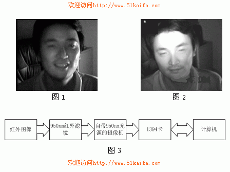
1) The area of ​​the face occupies a large proportion in the image. If the image is segmented with a reasonable threshold, the area with a value of 1 in the divided binary image is sorted from large to small according to the area of ​​the connected area, and the face is The area can be ranked in the first two places.
2) The amount of movement of the driver's head is larger than other places.
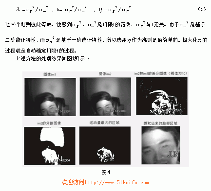
Therefore, the approach adopted in this paper is: first obtain the binary image binim of image im2 by appropriate threshold segmentation method, and then find the difference image difim between it and the image of the previous frame im1 (difim is the absolute value of the difference between im1 and im2. The binary image after the threshold is divided), the two connected regions s1 and s2 having the largest area in the binim are calculated; the motion amount of the two regions is calculated in the difference image difim, and an area in which the motion amount is larger is selected. The upper and left and right boundaries of the area are calculated, and the lower boundary is selected such that the area of ​​the face is square.
Since the light of the image changes greatly when the posture of the face changes, it is not feasible to use a fixed threshold. In this paper, the image is binarized by the category variance automatic threshold method. The principle of this method is as follows: 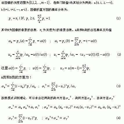
With the point (x, y) as the center, draw a circle with a certain radius, and store the points on the circle into the array in turn, and set the array to 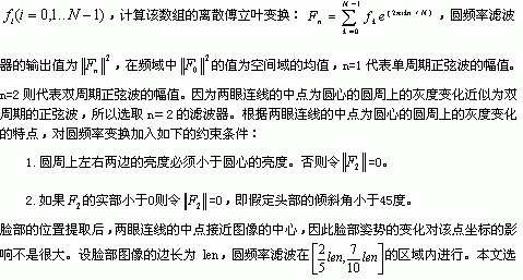
After positioning the eyebrows, this article uses the following method steps to locate the pupil center and calculate the pupil area.
1. According to this point, the approximate area where the eyes and eyebrows are located is selected, and 20 pixels from the upper and lower sides of the eyebrow are selected, and the horizontal distance is in the image area of ​​[7, 40].
2. Horizontal integral projection in the selected image area is G(y)=  For the mean filtering of G(y), the integral of the eye and the eyebrow is relatively small, and the brightness of the eyelid between the two is relatively large, so we calculate the peak between the two troughs in G(y) as the eye area. The boundary is taken from the upper boundary plus 15 as the lower boundary.
3. The generalized symmetric transformation is performed in the eye region to calculate the pupil center. Since the region of the eye is small, the time complexity of the generalized symmetric transformation is  ( ), where n is the sum of the pixels of the image, m is the size of the model, but the calculated area is small, so it does not affect real-time. Here, the ellipse model is used to locate the center of the pupil. The long axis of the ellipse is a=6, and the short axis b=3 is the principle of generalized symmetric transformation [5].
4. The gradation of the upper and lower 10 pixels, the gradation of the left and right 10 pixel regions is converted to [0, 1], and 0.4 is the threshold segmentation image. Calculate the area of ​​the pupil. 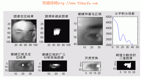
In order to further improve the processing speed, this paper does not perform the above steps for each frame of image, but estimates the area of ​​the next frame of eyes and eyebrows after positioning the center position of the eye, and uses the integral projection and generalized symmetry to locate the center of the eye. Only when the difference in brightness around the eyes of two consecutive frames is too large, the eyes are positioned in all of the above steps over the entire image range. Figure 5 shows the process of positioning and pupil area calculation for the right eye.