Henan HuaYang Copper Group
Co.,Ltd specialized in
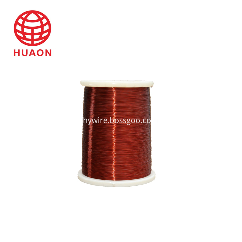
producing enameled Copper Wire for 25 years ,Products including PEW
enameled copper wire, Eiw Enameled Copper Wire, EI/AIW enameled
copper wire, EIW/A Enameled Copper Wire,and Enameled and glass-fiber
copper wire.
According to the characteristics of motor,
transformer, automotive electrical and high-speed winding machine, we have
advantages in resilience, breakdown voltages and have imported machine to
protect the quality of Enameled copper wire.
After 25 years of efforts, we have good reputation
from foreign and domestic.
Product Feature.
Enameled
Copper Wire
Conductor
Copper
Dimension
Diameter(mm):
0.15 ~ 3.0
Thermal
Class(℃)
130(Class
B); 155(Class F); 180(Class H); 200(Class C); 220(Class C+);
Standard
IEC;
Packing
PT4
– PT200 or ply-wood spool
Application
Transformer;
motor; generator; modern instrument; welding machine and so on
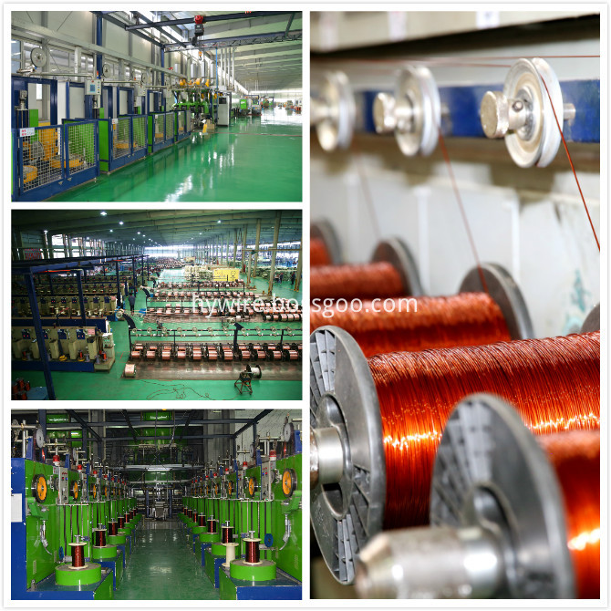
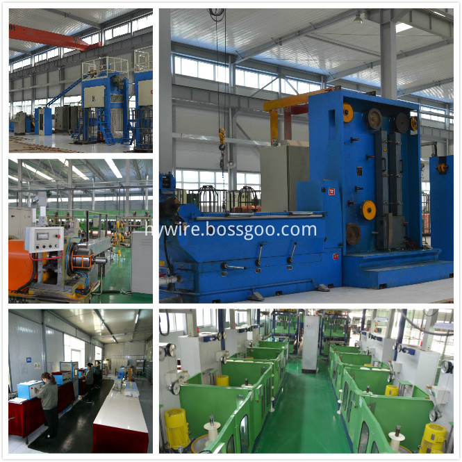
For quality of Enameled Copper Wire, we have
imported machine and R&D. we checked every spools of products after finishing
the products.
'Quality and efficiency' is our principle.
Enameled Copper Wire Enameled Copper Wire,Enameled Magnetic Copper Wire,Rewding Enameled Copper Wire,Winding Enameled Copper Wire HENAN HUAYANG ELECTRICAL TECHNOLOGY GROUP CO.,LTD , https://www.huaonwire.com
About Enameled Copper Wire

About
Factory.


Conventional gallium nitride (GaN) LED components are usually based on sapphire or silicon carbide (SiC) because the two materials have a good lattice matching with GaN, and the substrate is usually 2" or 4" in size. The industry has been working to develop GaN with more abundant silicon wafers (6" or larger) because silicon substrates can significantly reduce costs and can be fabricated on automated IC production lines. It is reasonable to estimate Traditionally, this substrate can save 80% of the cost.
However, the problem with the silicon substrate is that there is a serious mechanical and thermal mismatch with GaN, which causes severe warpage of the wafer constituting the LED element and deterioration of the quality of the crystal material. Silicon-based GaN technology from Cambridge University's derivative company CamGan (acquired by Plessey in 2012) has now solved this mismatch and has been successfully applied to its wafer processing plant in Plymouth, UK. As a result, the industry's first low-cost, entry-level commercial silicon-based GaN LED is now on the market. The primary products are mainly for the indicator light and key lighting market. The luminous efficiency is 30-40lm/W, and 70lm/W products will be launched in the third and fourth quarters of this year, which will be supplied to more general lighting markets.
Figure 1: Vertical LED production flow chart.
GaNonSiGthth: Silicon-based GaN growth
Mirrorlayeradded: added mirror layer
Wafer: Using Wafers
Flipbondedwafer: flip-chip bonded wafer
Substrateremoval: substrate removal
Metallisationandsurfacetexturing: spraying metal layers and surface textures
The use of silicon substrates to produce LEDs requires some process steps to overcome the silicon material absorption problems inherent in the architecture and to create efficient components. In the wafer processing process (shown in Figure 1), a vertical LED component is designed on a GaN architecture (6"-based silicon wafer grown by MOCVD. Next, a highly reflective contact is deposited and adhered. (The reflectivity is typically 95%) and then some metal layers are made to paste the wafer onto the replacement substrate.
This is followed by a wire bond that is used in the casting of the solder layer with a conductive and thermally conductive fusible gold tin layer (re-melting temperature of about 280 ° C) along with other metal layers to serve as a carrier between the solder metal and the component or replacement. After the bonding wire is completed, the parent wafer is removed, and the seed layer for epitaxial growth of the GaN layer is exposed. The wafer is flipped for the next LED element patterning process. The metal coating is patterned on the wafer and placed over the barrier layer to minimize the amount of light-emitting area coverage. Most of the current is delivered by the top metal (usually 2m). Finally, photo-extraction patterning is performed and etched into the GaN layer (exposed to the back of the bonding wire) to remove the parent wafer. The final step is especially critical for remote phosphor applications because it enables illumination pattern control of blue LEDs.