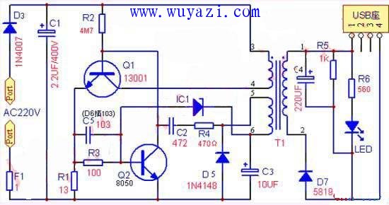
In order to simplify the circuit and achieve the purpose of learning, the resistor F1 of 1 ohm is used as a fuse, and the rectification is completed by a diode D3. After the power is turned on, C1 will have a DC voltage of about 300V, and the current will be supplied to the base of Q1 through R2. The emitter of Q1 has R1 current detecting resistor R1. After the base of Q1 is energized, it will pass T1 (3, 4). Producing a collector current and simultaneously generating an induced voltage on (5, 6) (1, 2) of T1, the two secondary insulated coils of the same number of turns, wherein the T1 (1, 2) output is rectified by D7 After C4 filtering, the load is supplied to the load through the USB socket; wherein T1 (5, 6) is rectified by D6, filtered by C2, and passed through IC1 (actually 6.3V voltage regulator) and Q2 to form a sampling comparison circuit to detect the output voltage level; (5, 6), C2, and R4 also form a positive feedback circuit of the Q1 transistor, allowing Q1 to operate at high frequency oscillations, and continuously supply power to the T1 (3, 4) switch. When the output voltage rises due to any light load or high power supply voltage, T1 (5, 6), IC1 sampling comparison leads to Q2 conduction, Q1 base current decreases, collector current decreases, and load capacity becomes smaller. As a result, the output voltage is reduced; when the output voltage is reduced, Q2 is sampled and then turned off, Q1's load capacity becomes stronger, and the output voltage rises again; this acts as an automatic voltage regulator. Although this circuit has few components, it is also designed with overcurrent overload and short circuit protection. When the load is overloaded or short-circuited, the collector current of Q1 increases greatly, and the emitter resistance R1 of Q1 generates a higher voltage drop. The high voltage generated by this overload or short circuit will pass through R3 to make Q2 saturate, C4 is here. As a function of the acceleration capacitor, Q2 can be turned on as soon as possible, so that Q1 can stop output and prevent overload damage. Therefore, changing the size of R1 can change the load capacity. If the required output current is small, for example, only need to output 5V100MA, the resistance of R1 can be changed. Of course, if you need to output 5V500MA, you need to change R1 appropriately. Note: R1 will increase the possibility of burning Q1. If high current output is required, it is recommended to replace the high power tube in 13003 and 13007. Guangzhou Yunge Tianhong Electronic Technology Co., Ltd , https://www.e-cigarettesfactory.com
What role does R5 play? The T1 transformer is an inductive component. Q1 operates in the switching state. When Q1 is turned off, T1 will generate a high electromagnetic induction voltage. In the absence of load, a high voltage may be induced at the Q1 collector. This voltage may be Up to 1000 volts or more, this will cause Q1 breakdown damage. Now with R5, the circuit does not appear to be unloaded, so Q1 will not be damaged by the high voltage breakdown of the collector. Therefore, this resistor has very subtle but Another very important role, without this resistor and R6 and LED, Q1 is very dangerous, can be damaged in minutes and seconds, at the same time, the no-load voltage can even be as high as 6V or even 7V.