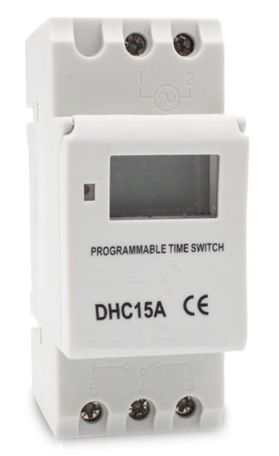
Digital Timer automatically turns the power of various powered devices on and off according to the time set by the user. The control object can be a street lamp, a neon lamp, an advertising sign lamp, a production device, a broadcast television device, and the like, and all power devices and household appliances that need to be turned on and off periodically. Built-in 1.2V/40mA can be charged, high precision, industrial grade chip, strong anti-interference.
Timer Relays,Time Delay Relay,Digital Timer Switch,24 Hr Timer Relay Ningbo Bond Industrial Electric Co., Ltd. , https://www.bondelectro.com
The register map DS1340's control register (address 07h) is used to control the operation of the FT / OUT pin and program the desired clock calibration. The detailed DS1340 register mapping table is given below.
Table 1. Register map Address Bit 7 Bit 6 Bit 5 Bit 4 Bit 3 Bit 2 Bit 1 Bit 0 FuncTIon Range 00H acTIve-low EOSC 10 Seconds Seconds Seconds 00-59 01H R / W 10 Minutes Minutes Minutes 00-59 02H CEB CB 10 Hours Hours Century /
Hours 0-1;
00-23 03H R / W R / W R / W R / W R / W Day Day 01-07 04H R / W R / W 10 Date Date Date 00-31 05H R / W R / W R / W 10 Month Month Month 01-12 06H 10 Year Year Year 00-99 07H OUT FT S CAL4 CAL3 CAL2 CAL1 CAL0 Control 08H TCS3 TCS2 TCS1 TCS0 DS1 DS0 ROUT1 ROUT0 Trickle
Charger 09H OSF 0 0 0 0 0 0 0 Flag
Output control (OUT): This bit is used to control the output level of the FT / OUT pin when the FT bit is set to zero. When FT = 0, if OUT = 1, the logic level of the FT / OUT pin is 1; if OUT = 0, the logic level of the FT / OUT pin is 0.
Frequency test (FT): When this bit is 1, the FT / OUT pin flips at a frequency of 512 Hz; when FT is zero, the OUT bit controls the state of the FT / OUT pin.
Calibration sign bit (S): When this bit is logic 1, it indicates that the RTC is positively calibrated; logic 0 indicates that the clock is negatively calibrated. For details about these control bits, please refer to the crystal calibration section.
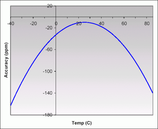
Calibration bits (CAL4 to CAL0): These bits are set to any value from 0 to 31 in binary format. For details about these control bits, please refer to the crystal calibration section. Typical crystal characteristics Crystal oscillator is one of the most accurate circuits to provide fixed frequency output. The accuracy of RTC depends mainly on the accuracy of the crystal oscillator. The curve of the tuning fork crystal frequency with temperature is parabolic, as shown in Figure 1. 
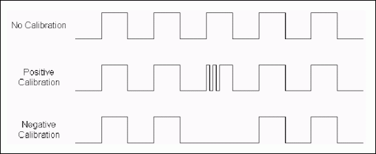
Figure 1. Standard tuning fork crystal characteristics. The purpose of the crystal calibration calibration circuit is to adjust the position of the curve at a selected temperature to achieve zero ppm accuracy. This is achieved by increasing or decreasing the count value of the oscillator frequency division chain. The number of masked (subtracted during negative calibration) or inserted (added during positive calibration) is set by a 5-bit value, which is loaded in the calibration bits of the control register (CAL4: CAL0). Increasing the number will speed up the clock (the curve moves up), and decreasing the number will slow down the clock (the curve moves down). The figure below shows the clock adjustment chart during positive and negative calibration. 
With the binary format from 0 to 31, the calibration bit can be set to any value. Bit 5 of the control register (S) is the sign bit. The value of the S bit is 1 for positive calibration, and the value 0 is for negative calibration. Every 125,829,120 actual 32,768 Hz oscillator cycles (64 minutes), each calibration step increases by 512, or decreases by 256 oscillator cycles. This corresponds to an adjustment of + 4.068ppm or -2.034ppm per calibration step. If the oscillator is operating at 32,768 Hz, each additional 31 calibration bits will show +10.7 or -5.35 seconds per month (+5.5 or -2.75 minutes per month). Table 2 shows the adjustment of each value in the calibration register.
Table 2. Calibration adjustment values
Deciding the clock error Before setting the calibration value, you must first determine the number of calibrations required. When the FT bit (bit 6) of the control register is set, the FT / OUT pin (pin 7) generates an uncalibrated 512Hz clock. This frequency determines the frequency error of the crystal oscillator. Sign CalibraTIon Adjustment Sign CalibraTIon Adjustment Accuracy (ppm) Time (sec / month) Accuracy (ppm) Time (sec / month) 0 00000 0 0 1 00000 0 0 0 00001 -2 -5 1 00001 4 11 0 00010 -4 -11 1 00010 8 twenty one 0 00011 -6 -16 1 00011 12 32 0 00100 -8 -twenty one 1 00100 16 43 0 00101 -10 -27 1 00101 20 54 0 00110 -12 -32 1 00110 twenty four 64 0 00111 -14 -37 1 00111 28 75 0 01000 -16 -43 1 01000 33 86 0 01001 -18 -48 1 01001 37 96 0 01010 -20 -54 1 01010 41 107 0 01011 -twenty two -59 1 01011 45 118 0 01100 -twenty four -64 1 01100 49 128 0 01101 -26 -70 1 01101 53 139 0 01110 -28 -75 1 01110 57 150 0 01111 -31 -80 1 01111 61 161 0 10000 -33 -86 1 10000 65 171 0 10001 -35 -91 1 10001 69 182 0 10010 -37 -96 1 10010 73 193 0 10011 -39 -102 1 10011 77 203 0 10100 -41 -107 1 10100 81 214 0 10101 -43 -112 1 10101 85 225 0 10110 -45 -118 1 10110 89 235 0 10111 -47 -123 1 10111 94 246 0 11000 -49 -128 1 11000 98 257 0 11001 -51 -134 1 11001 102 268 0 11010 -53 -139 1 11010 106 278 0 11011 -55 -144 1 11011 110 289 0 11100 -57 -150 1 11100 114 300 0 11101 -59 -155 1 11101 118 310 0 11110 -61 -161 1 11110 122 321 0 11111 -63 -166 1 11111 126 332
For example, if you use FT, a reading of 512.01024Hz means that the frequency error of the oscillator is + 20ppm, and you need to load a value of -10 (00 1010) in the S and calibration bits. Writing data to the control register clears the prescaler and immediately generates an output frequency of 512 Hz (the frequency of the FT / OUT pin decreases). Setting or changing the calibration bit will not affect the frequency of the FT / OUT output pin.

Abstract: The DS1340 serial interface real-time clock (RTC) provides software clock calibration functions to provide crystal oscillator and temperature change compensation for the system. This application note mainly describes how to use this function to improve the timing accuracy.