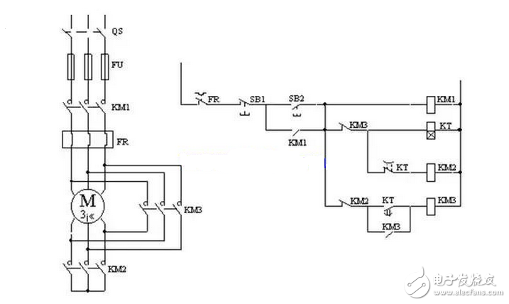
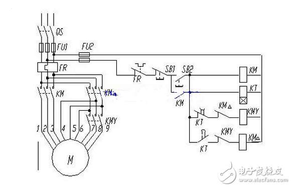
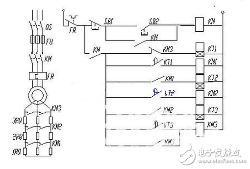
The secondary of the autotransformer typically has three taps, resulting in three voltages of varying values. When used, it can be flexibly selected according to the requirements of starting current and starting torque. When the motor starts, the voltage obtained by the stator winding is the secondary voltage of the autotransformer. Once the start is completed, the autotransformer is cut off, and the motor is directly connected to the power supply, that is, the primary voltage of the autotransformer is obtained, and the motor enters full voltage operation. This autotransformer is often referred to as a start compensator. The design idea of ​​this line is basically the same as that of the series resistance starting circuit, and the motor starting process is completed according to the principle of time. Figure 4 Y-△ step-down starting control circuit When the start button SB2 is pressed, the coil of the contactor KM1 is energized, and the motor M is connected to the power source. At the same time, the time relay KT and the contactor KM2 coil are energized. The contactor KM2 coil is energized, its normally open main contact is closed, and the motor M stator winding is operated under a star connection. The normally closed auxiliary contact of the KM2 is disconnected, ensuring that the contactor KM3 is not energized. The normally open contact of the time relay KT is time-delayed; the normally closed contact delay is opened, the KM2 coil power supply is cut off, the main contact is opened and the normally closed auxiliary contact is closed. The contactor KM3 coil is energized and its main contact is closed, causing the motor M to switch from a star start to a delta run. Parking: Press SB1 auxiliary circuit to cut off, each contactor is released, motor is powered off and parked The line has an auxiliary contact interlock between KM2 and KM3 to prevent them from causing short circuit at the same time; in addition, after the line is turned into the triangle connection operation, the normally closed contact of KM3 is disconnected, and the time relay KT and the contactor KM2 are cut off to avoid The KT and KM2 coils run for a long time and consume energy and prolong their life. The advantage of the three-phase squirrel-cage asynchronous motor adopting Y-△ step-down starting is that when the stator winding is connected by star, the starting voltage is 1/3 when the triangle connection is directly used, and the starting current is 1/ when the delta connection is used. 3, thus the starting current characteristics are good, the line is simpler, and the investment is less. The disadvantage is that the starting torque is also reduced to 1/3 of the delta connection, and the torque characteristics are poor. Therefore, the line is suitable for light load or no-load start. In addition, it should be noted that the Y-△ connection should pay attention to the consistency of its rotation direction. As mentioned above, the Y-△ step-down start has many advantages, but the fly in the ointment is that the starting torque is too small. Can design a new step-down starting method, which has the advantages of small starting current of star connection, no special starting equipment, and large starting torque of delta connection, in order to complete a more ideal starting process. What? △ - △ step-down start can meet this requirement. At the time of starting, a part of the stator winding of the motor is connected in a star shape, and the other part is connected in a triangle shape. After the start is completed, it is converted into a delta connection, and the conversion process is still controlled according to the time principle. Figure 5 shows the connection of the stator windings of the motor. Figure (a) is the original state. Figure (b) shows the state in which the extended triangle is joined at the time of starting. Figure (c) shows the normal operating state. This type of motor has a total of nine tapping head control systems, changing the stator winding tap ratio (ie, the ratio of N1 to N2), can change the voltage on the stator windings at start-up, thus changing the starting current and starting torque. However, in general, the tap ratio of the motor has been fixed, so only a limited variation is made within the range of these tap ratios. For example, by phasor calculation, if the line voltage is 380V, when N1/N2=1/1, the tap percentage is 71c/o similar to the autotransformer, the phase voltage is 264V; when N1/N2=1/2 Similar to the autotransformer tap percentage 78c/o, the phase voltage is 290V; when N1/N2=2/1, the tap percentage is similar to the autotransformer 66c/o; Y-△ connection, similar to the autotransformer The percentage of taps is 58c/o. The circuit in which the stator winding is in the Δ-Δ connection is shown in Fig. 6. Metal Dome Tactile Membrane Switch Membrane Switch,Membrane Switch Manufacturer,Metal Dome Membrane Switch,Membrane Keypad,Membrane Keyboard KEDA MEMBRANE TECHNOLOGY CO., LTD , https://www.kedamembrane.com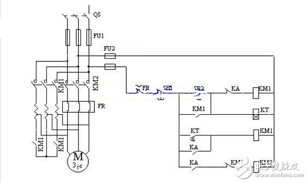
1. Electronic characteristics
Circuit rating
35V (DC), 100mA, 1W
Contact resistance
10Ω~500Ω (According the trace length and materials)
Insulation resistance
> 100MΩ 250V DC
Contact bounce
≤ 5ms
Dielectric withstand
250VRms (50~60Hz 1min)
Life expectancy
Flat type ≥ 5 million times, tactile type ≥ 1 million times
2. Mechanical Properties
Actuation force
Flat type: 57-284g (2-10 Oz), tactile type: 170~397g (6~14 Oz)
Switch stroke
Flat type: 0.1~0.5mm, tactile type: 0.6~1.5mm
3. Environmental parameters
Operating Temperature
-40°C~+80°C
Storage temperature
-40°C~+85°C
Humidity
40°C, 90% ~95%, 240 hours
In the control circuit of the autotransformer step-down starting, limiting the motor starting current is achieved by the step-down action of the autotransformer. The primary of the autotransformer is connected to the power supply, and the secondary of the autotransformer is connected to the motor.