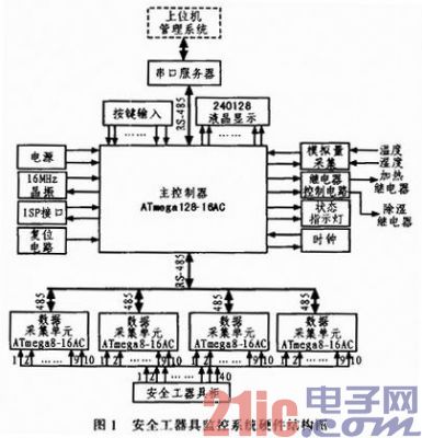
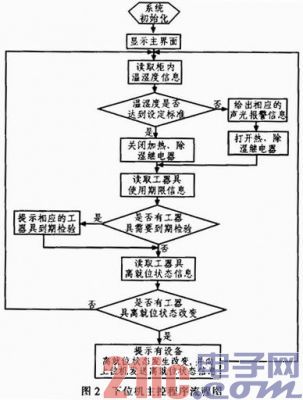
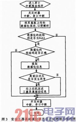
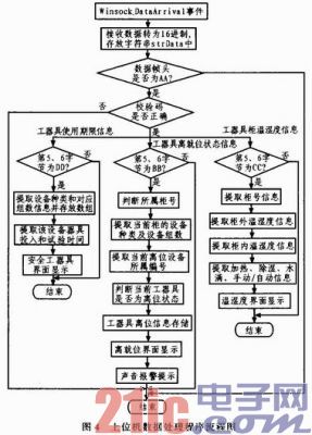
As we all know, safety is an eternal theme for power companies, and the quality of safety tools will directly affect the safety of personnel and equipment in the production process of power companies. The author puts forward a design scheme of safety equipment monitoring system based on AVR single-chip microcomputer, which mainly monitors the information of the safety equipment from the in-position state, the effective use period and the temperature and humidity conditions in the safety tool cabinet. The automatic adjustment of the temperature and humidity in the safety tool cabinet can automatically record the relevant information of the safety tool. This paper first expounds the overall structure of the system, and then discusses the hardware design and software design of the system in detail. 1 Overall structure of the safety equipment monitoring system 1.1 System Structure The safety tool monitoring system designed in this paper is mainly divided into two parts: data acquisition of lower computer and data management of upper computer. The two communicate through the network. The system first collects the relevant quantities of the safety tool cabinet through the data acquisition board, and then processes the collected data to be processed accordingly, and then transmits it to the upper computer management system through the serial port server, and the upper computer obtains the data and performs corresponding processing. Each safety tool cabinet requires 40 data acquisition ports to collect the in-position status information of the safety tools. When the safety tool's in-position state changes, the data acquisition board will collect this information and then pass it to the upper computer management system for processing. When the temperature and humidity in the cabinet do not reach the set standard, the system controls the heating and dehumidifying device to adjust the temperature and humidity in the cabinet. When the host computer management system receives the data transmitted by the lower computer, it starts to perform corresponding processing: backing up the in-position status information of the safety tool to facilitate historical inquiry; the use condition of the safety tool is effective. Information such as the period of use and the temperature and humidity conditions in the cabinet are displayed in real time on the user interface so that the staff can monitor the system. 1.2 System function The main functions implemented by the system are: 1) Real-time monitoring of the safety status of the safety tools. 2) Real-time monitoring of temperature and humidity conditions in the safety tool cabinet. 3) Real-time monitoring of the effective use period of safety equipment. 2 Hardware design of safety equipment monitoring system The main function of the hardware part of the system is to realize the detection of the safety status of the safety tool, the temperature and humidity in the cabinet, and the automatic control of the heating and dehumidifying device, and display the relevant information on the liquid crystal display in real time. The system hardware structure is shown in Figure 1. The system selects ATmega128-16AC of AVR series MCU as the main controller and ATmega8-16AC as the data acquisition controller. The AVR microcontroller is an enhanced RISC reduced instruction set high-speed 8-bit microcontroller with built-in Flash. It uses a Harvard architecture internally and has a clock speed of 16 MHz. The main control board needs to control 4 data acquisition boards to act on the same safety tool cabinet. The infrared reflection type detection method is used to detect the safety tool from being in the state of being in position. When the safety tool is borrowed or returned, the level fed back by the infrared reflection device is changed, and we pass the detection level. To determine the position and disengagement of safety equipment. The main control board acquires the data obtained by the data acquisition board through the RS-485 interface in a polling manner. After receiving the collected data, the main control board performs corresponding processing: displaying the specific information of the safety tool in position on the liquid crystal display, so that the staff can know the usage status of the safety tool in real time; The bit status information is passed to the upper computer management system for corresponding processing. 3 Software design of safety equipment monitoring system The software design of the safety tool monitoring system mainly includes three parts: the communication protocol design between the lower computer and the upper computer, the lower computer program design and the upper computer program design. 3.1 lower computer program design The lower position machine mainly completes the collection and display of the information on the safety status of the safety tool, the collection and adjustment of the temperature and humidity in the safety tool cabinet, and sends relevant information such as the safety tool to the host computer management system. deal with. 1) Design of the master program of the lower computer Only when the upper computer management system needs it, the effective service life of the safety tool and the temperature and humidity information in the cabinet will be sent to the upper computer management system. The flow chart of the main control program of the whole lower computer is shown in Figure 2. 2) Design of data processing program for lower computer acquisition The time interval for data acquisition of the lower computer is controlled by a timer. The data acquisition command is sent to the data acquisition board by the lower control unit main control board through RS-485. The collected data is also transmitted back to the main control board for processing by RS-485. . The process of processing the safety tool from the in-position state of the main control board is shown in Figure 3. 3.2 PC programming The main function of the upper computer management system is to realize the processing of the data transmitted from the lower computer: display the information of the safety status of the safety tool in the form of a user interface to the user, so that the staff can know the usage of the working instrument in time, and The off-position status information of the related tools is saved so that the user can make a history. The process of processing data by the host computer is shown in Figure 4. The event triggering method is used to process the data transmitted by the lower computer. When data is transmitted, the data processing flow is entered: firstly, the data start character and check code are determined. Is it correct, only when the two are correct, the next step of the data packet will be processed, otherwise the whole process of data processing will be ended, waiting for the arrival of new data; then the operation instructions in the data will be judged, when the data information and the required When the information does not match, the entire data processing flow is terminated, waiting for the arrival of new data; then corresponding processing is performed according to different data information; after the data processing is completed, waiting for new data to arrive. 4 Conclusion The safety tool monitoring system based on AVR microcontroller designed in this paper can effectively realize real-time monitoring of safety tools, including the use of safety tools, effective monthly deadlines, environmental conditions, etc. Automatic adjustment of ambient temperature and humidity; automatic storage of information related to safety tools, providing historical query function. This paper proposes a safety tool monitoring method in order to realize the scientific and efficient management of safety tools, which is an important part of power companies to achieve safe production and scientific management. Easy Electronic Technology Co.,Ltd , https://www.yxpcelectronicgroups.com


