The electronic program controller of the washing machine introduced in this example can replace the clockwork timer or electric program controller of the ordinary washing machine. GALOCE S-beam Load Cells receive tension or compression output readings. It provide superior performance in an compact, versatile package. They are are widely used in small hopper and tank weighing systems, hybrid systems with lever work, belt weighers and other load carriers with multiple load cells.The S beam Load Cell is normally used in tensions applications where you will experience statis and dynamic loads. They are primarily used for mechanical-to-electronic scale conversions and specific weighing applications like cranes, big bags etc. Capacities vary from 25kg to 30t. Zemic offers a wide range of S-type loadcells made from alloy steel and stainless steel. Also a programm of accessories is available like hooks, eyes and rod ends. S Beam Load Cell,S Type Load Cell,S load cell,S Shaped Load Cell,Tension load cell GALOCE (XI'AN) M&C TECHNOLOGY CO., LTD. , https://www.galoce-meas.com
Circuit Operation Principle The electronic program controller circuit of the washing machine consists of a power supply circuit, a multivibrator, a trigger and a control execution circuit, as shown in Figure 3-205. 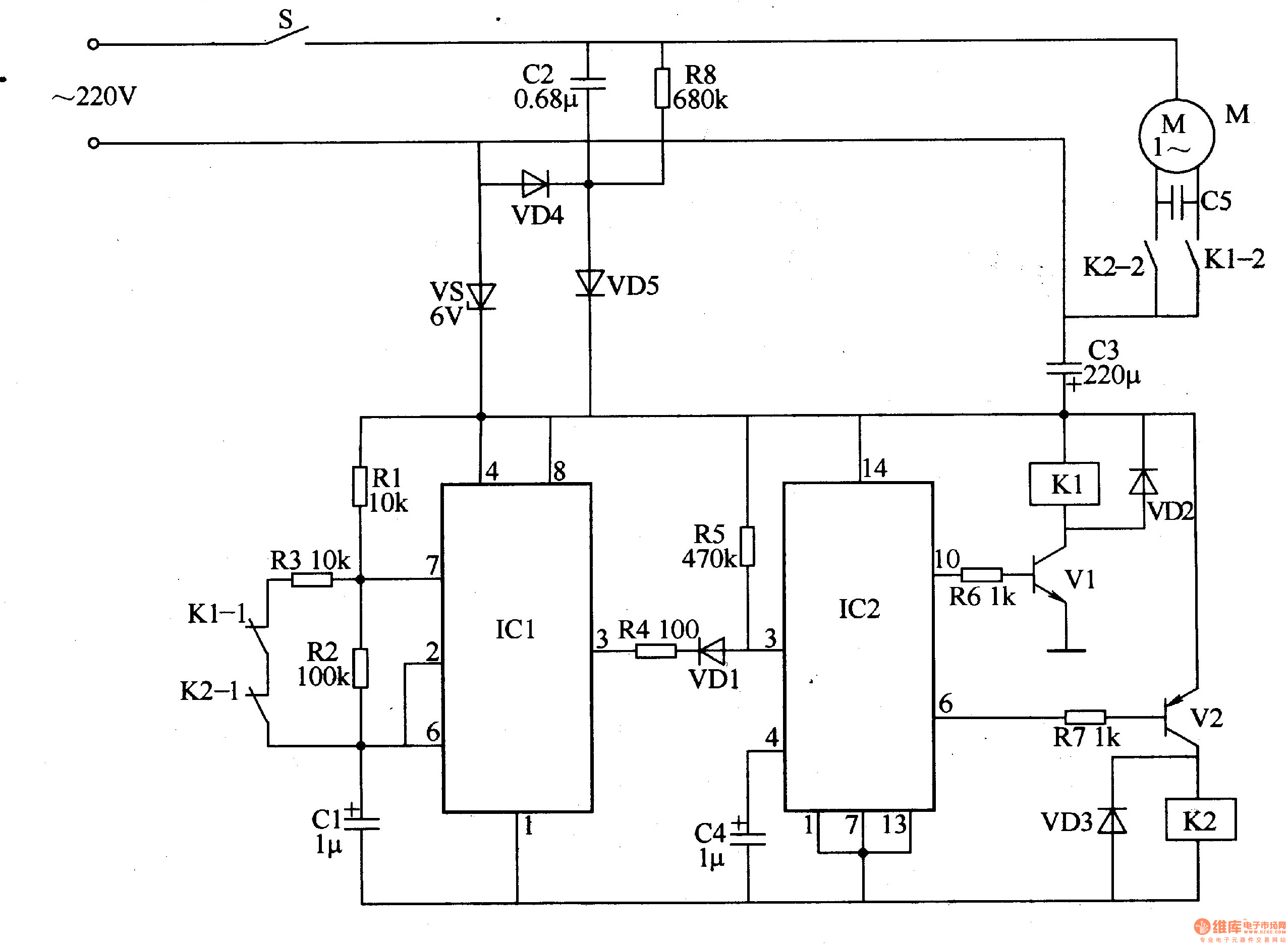
The power circuit is composed of a power switch S, a step-down capacitor C2, a resistor R8, a rectifier diode VD4, a VD5, a Zener diode VS, and a filter capacitor C3.
The multivibrator is composed of a time base integrated circuit ICl, a resistor Rl-R3, a capacitor C1, and normally closed contacts Kl-1, K2-1 of the relays K1, K2.
The flip-flop is composed of a voice control integrated circuit IC2 (internal consisting of a three-stage mode signal amplifier, a shaping circuit, a frequency selection circuit, a negative pulse trigger and an output driving circuit), a diode VD1, a resistor R4, R5 and a capacitor C4.
The control execution circuit is composed of transistors V1, V2, relays K1, K2, resistors R6, R7, and diodes VD2, VD3.
M is the washing machine washing motor, and C5 is its starting/running capacitor.
Turn on the power switch S, AC 220V voltage through C2 step-down, VD4 and VD5 rectification, VS voltage regulation and C3 filtering, generate 6V DC voltage (Vcc), supply ICl, IC2 and control execution circuit.
When the power is turned on, the voltage at pins 2 and 6 of ICI is lower than Vcc/3, and the output of pin 3 is high. When the voltage at both ends of Cl is charged to 2Vcc/3, the circuit in ICl flips, and the 3 pin becomes low level, which makes VDl turn on. In IC2 (1C2 has three kinds of output states, each time a low-level trigger signal is received, The output of the output state changes once. The 3 pin generates a low-level trigger pulse. The 6-pin and 10-pin of IC2 are both low-level, VZ is turned on, KZ is connected, and its normally closed contact Kl-1 is disconnected. The open contact Kl-2 is turned on, and the motor M is energized to rotate forward.
At the same time, CI discharges the circuit in the 7th pin of lC1 via R2. When the voltage on Cl discharges to Vcc/3 (about 15s), the 3 pin of IC1 becomes high level, and Cl starts charging again. When the voltage at both ends of Cl is charged to 2Vcc/3, the 3 pin of IC1 becomes a low level, and after the IC2 is triggered, the 6 pin becomes a high level (the 10 pin remains low), so that VZ is cut off and KZ is released. The motor M stops.
Cl is quickly discharged to Vcc/3 (about 2s or so) via R2, IC1's 7-pin circuit and R3, and IC1's 3 pin outputs high-level hair, and Cl starts charging again. When Cl is charged to 2Vcc/3, the 3 pin of ICl becomes low level, after IC2 is triggered, 10 pin becomes high level (6 pin still maintains high level), then Vl turns on, Kl pulls, The motor M is reversed.
The following work process is the same as above. In this way, the washing machine continues to cycle through the program of 15s forward, 2s stop, 15s reverse, 2s stop, and 15s forward.
By changing the resistance of R2 appropriately, the time of motor M forward and reverse can be changed.
Component selection
Rl-R7 selects 1/4W carbon membrane resistor or metal membrane resistor for use; R8 selects 1/2W metal membrane resistor for use.
Cl, C3 and C4 are all made of aluminum electrolytic capacitors with a withstand voltage of 16V; C2 is a polyester capacitor or CBB capacitor with a withstand voltage of 630V.
VDI-VD3 selects 1N4148 type silicon switch diode for use; VD4 and VD5 select 1N4007 type silicon rectifier diode for use.
VS selects 1W, 6V Zener diode.
Vl selects 59013 or C8050, 58050 silicon NPN transistor; VZ selects 59012 or C8550, 58550 silicon PNP transistor.
ICl selects NE555 type time base integrated circuit; IC2 selects BH-SK-T type sound control integrated circuit.
Kl and K2 use JQX4F type 6V DC relay.