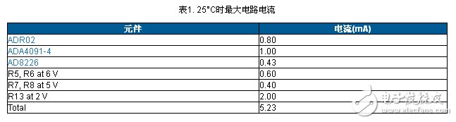
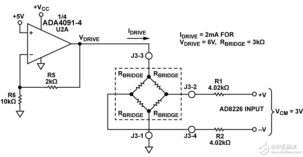
First, circuit functions and advantages The circuit shown in Figure 1 is a flexible current transmitter that converts the differential voltage output of the pressure sensor to a 4 mA to 20 mA current output. Optimized for a variety of bridge voltage or current-driven pressure sensors, this circuit uses only five active devices with a total unadjusted error of less than 1%. The power supply range is 7 V to 36 V, depending on the component and sensor driver configuration. The circuit's inputs are ESD-protected and provide voltage protection above the supply rail, making them ideal for industrial applications. Figure 1. Pressure sensor signal conditioning circuit with 4 mA to 20 mA output (shown as sensor voltage drive mode), schematic diagram: all connections and decoupling not shown) Second, the circuit description This design provides a complete 4 mA to 20 mA transmitter pressure sensor measurement solution. There are three important circuit levels: sensor excitation drive, sensor output amplifier, and voltage-to-current converter. The total current required by the circuit (excluding bridge drive current and output current) is 5.23 mA (max), as shown in Table 1. Incentive: Voltage Drive Configuration Voltage driven or current driven, depending on the selected pressure sensor. The circuit uses one-quarter of the ADA4091-4 (U2A) and selects different configurations via switch S1, supporting one of two options. Figure 2 shows the voltage-driven configuration with the S1 position closest to the identification mark (see the complete circuit layout and schematic in the CN0295 Design Support Package: http:// Voltage drives typically use this stage of gain (1 + R5/R6) is configured as a 6 V bridge drive voltage. Other drive voltages can be obtained by appropriately changing the resistance ratio: Note that the supply voltage, VCC, should be at least 0.2 V above the bridge drive voltage to allow U2A to have sufficient headroom. ADA4091-4: This circuit selects the operational amplifier ADA4091-4 because of its low power consumption (250 μA per amplifier), low offset voltage (250 μV), and rail-to-rail input and output characteristics. Because of the accuracy of the ADR02 (Class A: 0.1%, Class B: 0.06%) and low quiescent current (0.8 mA), the ADR02 is selected as the 5 V reference. Figure 2. Sensor Voltage Drive Configuration (Simplified Schematic: All Connections and Decoupling Not Shown) The ONU in EPON adopts the mature technology Ethernet protocol, which can realize low-cost Ethernet layer 2 and layer 3 switching functions. This kind of ONU can provide shared high bandwidth for multiple end users through cascading. In the communication process, no protocol conversion is needed, and the transparent transmission of user data can be realized. ONU also supports other traditional TDM protocols without increasing the complexity of design and operation. Epon Onu 1ge 1fe 1pots,1GE 1FE 1POTS EPON ONU,Epon Voip Onu,Pots Port,Voice Port Shenzhen GL-COM Technology CO.,LTD. , https://www.szglcom.com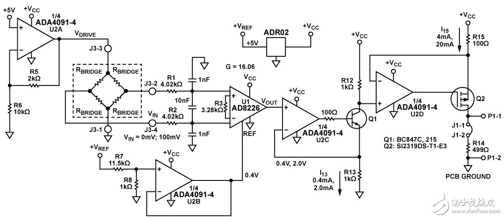
![]()
![]()
![]()
The OLT and all ONUs in EPON are managed by the network element management system, and the network element management system provides the operating interface with the core network of the service provider. The scope of network element management involves fault management, configuration management, billing management, performance management, and security management.
working principle:
1. Downstream data stream uses time division multiplexing (TDM) technology
During the transmission of the EPON signal, the downstream data is broadcast from the OLT to multiple ONUs. According to the IEEE802.3 protocol, the length of these data packets is variable, and the longest can reach 1518 bytes. Each data packet has its own destination address information, that is to say, the header of each packet indicates whether the data is for ONU1, ONU2 or ONUn. In addition, some packets can be sent to all ONUs, called broadcast packets, and some are sent to a special group of ONUs, called multicast packets. The data stream is divided into n independent signals after passing through the optical splitter, and each signal contains all specific data packets. When the ONU receives the data stream, each ONU extracts the data packets destined for itself according to the specific address information, and discards those data packets with different address information.
2. Upstream data flow uses time division multiple access (TDMA) technology
During the transmission of the EPON signal, the upstream data is sent from multiple ONUs to the OLT in a time division multiple access mode. Each ONU is assigned a transmission time slot. These time slots are synchronized. Therefore, when data packets are coupled to an optical fiber, different ONUs will not cause interference. For example, ONU1 transmits data packet 1 in the first time slot, ONU2 transmits data packet 2 in the second unoccupied time slot, and ONUn transmits data packet n in the nth unoccupied time slot, so that transmission conflicts can be avoided.