The MAX2606 adopts the SOT230-6 miniature package. The application circuit is shown in the figure. Its average frequency is set by L1. The inductance of 390nH can set the center frequency at 100MHz. Adjusting the potentiometer RP1 can select a channel as the transmit output power in the FM band of 88 to 108MHz. The output power is approximately -21dB for a 50Ω antenna. The two INPUTs in the picture are connected to the left and right line (LINE) output terminals of the power amplifier. The left and right channel audio signals are added through 22kΩ and attenuated by the potentiometer RP1. Then, they are sent to the internal oscillation circuit of MAX2606 through the ①pin. The modulated RF signal is output from the ⑥ pin to the transmitting antenna. Since the input signal amplitude is higher than 60mV, distortion will occur, so the potentiometer RP2 is used to attenuate the signal below this level. The transmitting antenna can be used as a 75cm section of wire. The launch distance is about 50 meters at this time. In order to ensure the best receiving effect, it is best to install it in parallel with the receiving antenna. MAX2606 can work on a single power supply of 3 to 5V, but it is best to use a stable voltage, especially the decoupling capacitor of 0.01uF can not be omitted to reduce frequency drift and noise. Follow WeChat Download Audiophile APP Follow the audiophile class related suggestion
A new FM transmitter chip MAX2606
MAX2606 is a new type of FM transmitter chip, which integrates a varicap diode voltage-controlled oscillator. Only a small number of external components are needed to form a high-quality FM transmitter. 


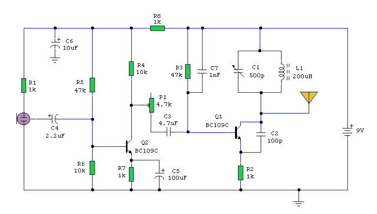
![[Photo] Two FM microphones with voltage regulator circuit](http://i.bosscdn.com/blog/20/06/41/52103537.jpg)
Interesting and informative information and technical dry goods
Create your own personal electronic circle
Lock the latest course activities and technical live broadcast
comment
Publish
[Photo] Two FM microphones with voltage regulator circuit
Published on 2006-04-15 21:00 • 234 times read