The electromagnetic cooker is an advanced electronic cooker for cooking food in modern homes by applying the principle of electromagnetic induction. It is very convenient to use and can be used for cooking, frying, frying, steaming, frying and other cooking operations. The power of the induction cooker is generally around 700--1800W. This article mainly introduces the use of SPMC65P2404 chip to achieve the design of induction cooker. SPMC65P2404 is an industrial control 8-bit single-chip microcomputer introduced by Sunplus. It has high cost performance and strong anti-interference ability, and is very suitable for industrial control and home appliance design. The induction cooker designed with SPMC65P2404 has the following properties: Figure 2â€1 Induction Cooker Heating Principle Figure 4â€1 System Block Diagram Click to see the original picture Figure 4â€2 Power Board Circuit Diagram Click to see the original picture Click to see the original picture Click to see the original picture Figure 4â€3 Circuit diagram of the main control board Figure 5â€1 Main program flow chart Click to see the original picture references [1] Xiao Jianhua, Jing Shunlin. The application and prospect of fuzzy control in home appliances. Journal of Wuyi University (Natural Science Edition), 2001 [2] Zhang Chao, Sun Zhifeng, Jin Gaoxian. Induction cooker main resonant circuit research and power control. Power Technology Applications, 2004. [3] VIPer12A datasheet http:// [4] R10 datasheet http://+_1193166.html. [5] COM datasheet http://+_1118194.html.
This 48 port USB charging station is used for the safe charging of iPhoneX, Samsung, Xiaomi, Huawei, laptop, tablet and other equipment. Portable -with a mini version of the family size desktop charger, plus compact size and lightweight weight make multiple USB charger stations very suitable for travel. Automatically detect and secure -automatically identify and adjust the best charging speed of the device. It will always collect it in the fastest and safest way. The USB charger has high current, charging and short -circuit protection, which can extend the battery life of the equipment. Environmental protection -compatibility, charging objects are not restricted, avoid using multiple chargers. Spend AC to USB data cables to USB charging sockets to meet the charging device. To MP3, MP4, DV, Bluetooth -free, all kinds of mobile phones, digital cameras and other digital products all 5V power supply costs.
48 Port Type-C Charger,Multiport Usb Charger,Usb Wall Charger Power Hub,48 Ports Usb Charging Station shenzhen ns-idae technology co.,ltd , https://www.best-charger.com
The induction cooker is divided into two categories, low frequency and high frequency, according to the current frequency in the induction coil. Compared with the high frequency electromagnetic cooker, the heating efficiency is high and the power is saved.
Classified by style, you can divide the following three.
Desktop Induction Cooker: It is divided into single head and double head. It has the advantages of convenient placement and strong mobility. Because the price is lower and more popular.
Buried induction cooker: put the whole induction cooker into the cabinet surface, and then dig a hole in the countertop to make the cooktop and the countertop face a plane. Industry experts recognize
For this installation method, only aesthetics is sought, but it is not scientific. A large part of the consumer group regards the induction cooker as a hot pot, and it is not convenient to bury the cooking.
Embedded induction cooker: can adapt to the needs of different pots, no longer have special requirements for the pot.
Six heating modes: hot pot, frying, stir-fry, grilling, cooking, roasting;
An automatic working mode: boiling water; maximum 720 minutes of timed start function; 2 hours automatic shutdown protection function; small object detection function, does not heat the unsuitable objects; the system uses overcurrent, overpressure, over temperature, etc. Kind of protection measures; Adopting switching power supply, the system can work normally in the voltage range of 180~250V; The system sets the fault alarm function to facilitate fault finding and overhaul; The system contains self-test procedures to facilitate production testing.
2 Induction cooker heating principle
Induction cookers use the principle of electromagnetic induction to heat food. The furnace surface of the induction cooker is a heat-resistant ceramic plate. The alternating current generates a magnetic field through the coil below the ceramic plate. When the magnetic field lines in the magnetic field pass through the bottom of the iron pot or the stainless steel pot, eddy current is generated, and the bottom of the pot is rapidly heated to reach the food. purpose.
The induction heating principle of the induction cooker is shown in Figure 2-1. The cooktop countertop is a high-strength, impact-resistant ceramic flat plate (crystallized glass). The high-frequency induction heating coil (ie, excitation coil) and high-frequency power conversion device are installed under the countertop. The corresponding control system has a flat-bottomed cooking pot on top of the countertop. 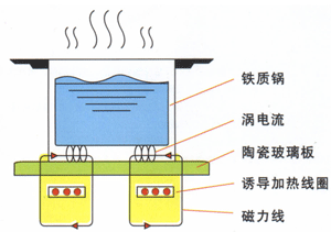
The working process is as follows: the current and voltage are converted into direct current by the rectifier, and the high frequency alternating current is converted into a high frequency alternating current exceeding the audio by the high frequency power conversion device, and the high frequency alternating current is applied to the flat hollow spiral induction heating coil, thereby generating High frequency alternating magnetic field. The magnetic lines of force penetrate the ceramic platen of the cooktop and act on the metal pan. In the cooking pot, there is a strong eddy current due to electromagnetic induction. The eddy current overcomes the internal resistance flow of the pot body to complete the conversion of electric energy to thermal energy, and the generated Joule heat is the heat source of cooking.
3 induction cooker design requirements
Induction cooker as a general household product, in addition to the basic heating function, its safety performance and stability can be the key to design.
The induction cooker is equipped with various protection devices, including small object detection, overheating automatic shutdown protection, overvoltage or undervoltage automatic shutdown protection, air-burning automatic stop heating protection, 2-hour power-off protection, 1~2 minutes automatic shutdown protection, and sound and light protection. Alarm display, etc. Taken together, the induction cooker can be evaluated by the following technical characteristics:
(1) Self-protection characteristics. The output switch tube is the key component of the induction cooker. It works in high voltage and high power state. It is limited by cost and device parameters. It is impossible to have a large margin when designing. Therefore, if the power supply voltage is too high and working during the working process. When switching, an instantaneous impact, an increase in current, an excessive rise in temperature inside the machine, a move of the iron pan away from the cooktop or no load, and the switch tube may be damaged. Therefore, it should ensure that the protection devices such as overpressure, overcurrent, overtemperature and pot detection are normal;
(2) The temperature control characteristics of the bottom of the pot. The heat at the bottom of the pot is directly transmitted to the cooking plate (ceramic glass), and the cooking plate is a heat conductive material.
Therefore, the heat sensitive component is generally installed at the bottom of the cooktop to detect the temperature of the bottom of the pan;
(3) Power stability. The induction cooker should have an automatic output power adjustment function to improve power supply adaptability and load adaptability;
(4) Electromagnetic compatibility. This performance involves interference with other home appliances and harm to the human body. The induction cooker is provided with an LC filter circuit in the power circuit and absorbs the leakage flux with a metal frame, and uses a pulse method to minimize the average radiation power;
4 system hardware design
The system adopts SPMC65P2404 as the main control MCU. The main modes are: keyboard scanning, pot temperature detection, IGBT temperature detection, current overcurrent detection, overvoltage and undervoltage detection, oscillation signal detection, fan control, digital tube display control, LED control, Buzzer control, system start control. 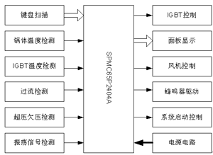
4.1 Power board circuit analysis 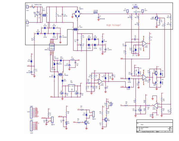
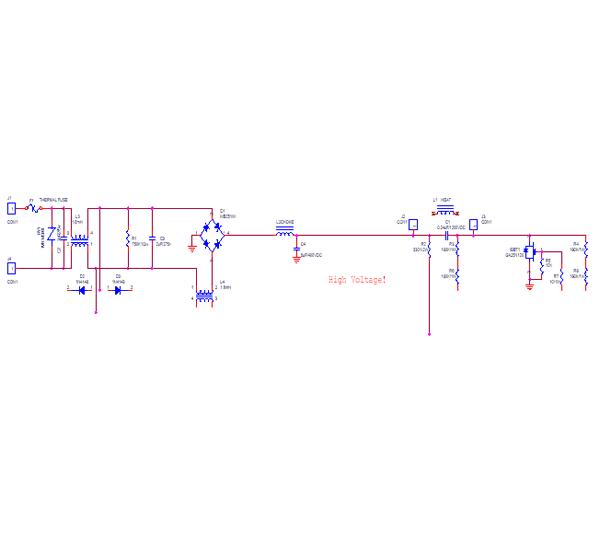
4.1.1 Heating coil working circuit
4.1.2 Switching Power Supply Circuit Section 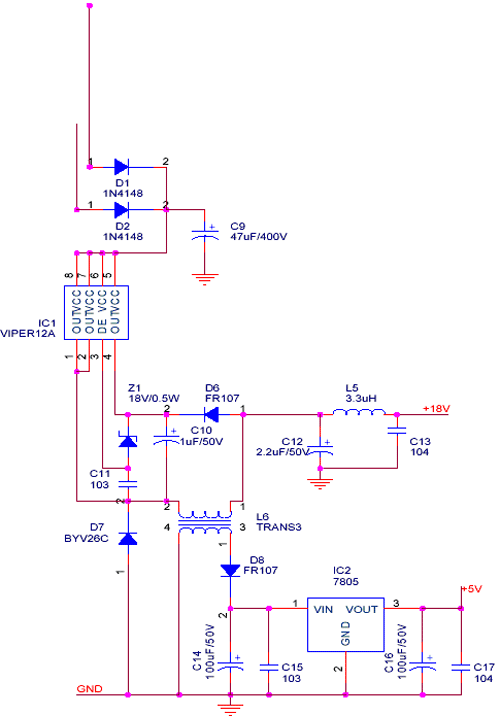
The switching power supply part adopts TI's latest integrated circuit VIPer12A to realize the output of different voltages. After the AC is connected, it is half-wave rectified and connected to the voltage input pin of VIPer12A. The output terminal is regulated by voltage transformer to obtain 18V and 5V DC power supply for ICs and other peripheral components.
4.1.3 Voltage value measurement circuit
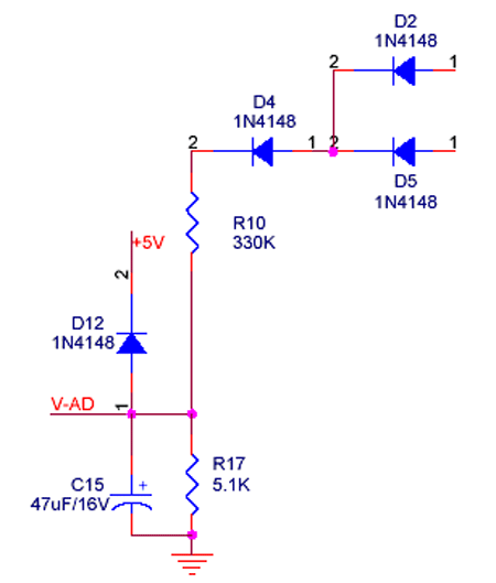
&n bsp; 4.1.4 Temperature measurement
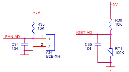
The IGBT and the bottom surface of the tile are tested by two thermistors to protect the IGBT and provide a reference for temperature control of the system.
4.1.5 IGBT control circuit
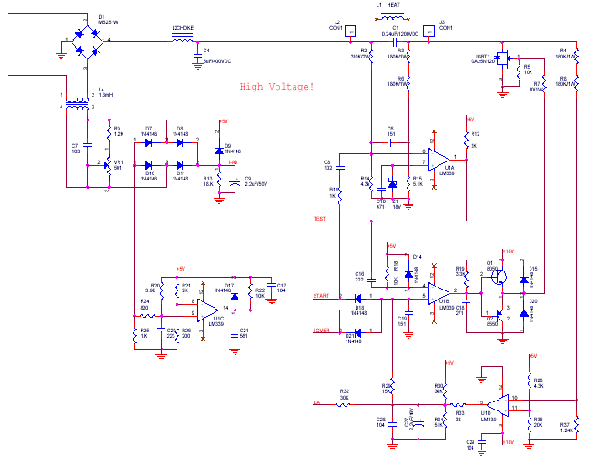
The circuit includes a current detecting portion. The current of the total circuit is reduced by a current transformer, and then converted into a direct current by a rectification to connect a resistor to the ground. The system determines the current of the loop by checking the voltage of the resistor terminal. At the same time, if the loop current exceeds a certain value, the protection signal at the other end is fed back to the control terminal of the IGBT, and the control signal is pulled low, so that the IGBT stops working and is sent to the MCU to stop the system and generate an alarm signal.
4.2 Control board circuit analysis 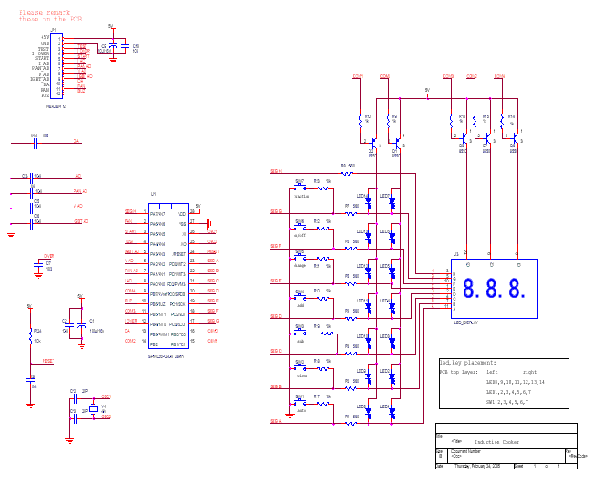
The main control board is mainly composed of MCU, digital tube, light-emitting diode, button and reset circuit. The digital tube adopts common anode type, the LED driving method is dynamic scanning, the button is multiplexed with SEG line, the COM port is controlled, and the SEG is read back. I/O of the data to scan the keys. The reset circuit is a low voltage reset circuit, and when the voltage is lower than 2.6V, the system generates a reset.
5 system software design
5.1 Program Process Analysis
The main process adopts a time-sharing structure, and different work is performed in each different time slice. The time slice can periodically refresh and scan the dynamically scanned LEDs to facilitate program control. Working in a round-robin manner, you can effectively use time resources. In the process, information is mainly passed to other modules by means of flags. 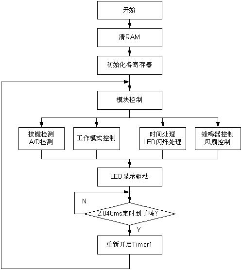
5.2 interrupt subroutine flow chart
The current overcurrent interrupt is the only interrupt of the whole system. When the interrupt is generated, the system immediately stops the control signal, and then sets the current overcurrent flag to let the system detect the state of the overcurrent in other places for 3 seconds. If so, the current is generated. The alarm signal of the flow stops the system.
5.3 &
Nbsp;Power adjustment module
The system needs to calculate whether the set power value has been reached according to the external voltage and current, and adjust the PWM value by comparing the power relationship to output a relatively constant power.
Assuming the external voltage is V1, the voltage value V2 detected by the MCU is calculated according to the circuit: V2=5.1*V1/(330+5.1), and the obtained A/D value DATA is: DATA="V2"*256/5 , The relationship between the external current and the test value of the MCU through the converted voltage is: External current value / converted voltage = 2.4.
According to the above relationship, the magnitude of the power value is converted: P=V*I=0.06*AD(V)*AD(I), push: AD(I)=100*P/(6*AD(V)), determine AD After (I), adjust the PWM value so that AD(I) reaches the calculated value.
5.4 System Resource Allocation
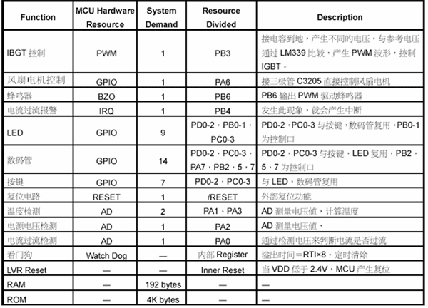
:
1 Introduction
The AC 220V is filtered by the front end and becomes a DC of about 310v through the rectifier bridge. The MCU controls the conduction and closing of the IGBT to control the working state of the heating coil.
8 times
Window._bd_share_config = { "common": { "bdSnsKey": {}, "bdText": "", "bdMini": "2", "bdMiniList": false, "bdPic": "", "bdStyle": " 0", "bdSize": "24" }, "share": {}, "image": { "viewList": ["qzone", "tsina", "tqq", "renren", "weixin"], "viewText": "Share to:", "viewSize": "16" }, "selectShare": { "bdContainerClass": null, "bdSelectMiniList": ["qzone", "tsina", "tqq", "renren" , "weixin"] } }; with (document) 0[(getElementsByTagName('head')[0] || body).appendChild(createElement('script')).src = 'http://bdimg.share. Baidu.com/static/api/js/share.js?v=89860593.js?cdnversion=' + ~(-new Date() / 36e5)];
48 Ports usb charging station