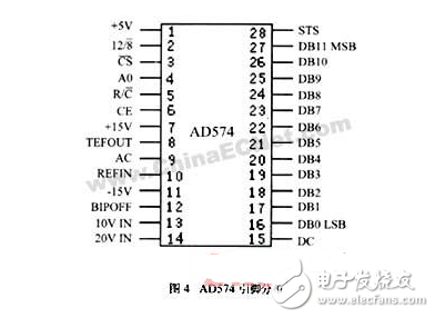
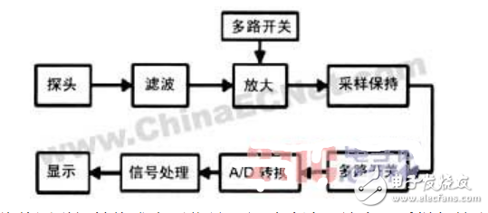
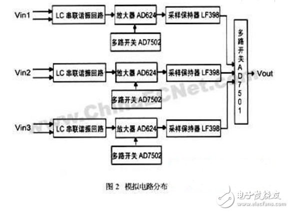
At present, the research and prevention of environmental electromagnetic pollution has attracted more and more people's attention. Electromagnetic biological effects have also become an important research direction in the field of electromagnetic compatibility research. Among them, the influence of power frequency electromagnetic fields generated by transmission lines on living organisms is the most concerned. One of the problems. However, at present, the measurement methods for environmental power frequency magnetic field are still lacking. In response to this need, we have developed a power frequency weak magnetic measuring instrument centered on the 8032 single chip microcomputer, which can measure from one millimeter to one thousand millimeters in height and the direction is unknown. The power frequency magnetic field can be used as an effective monitoring method for the environmental power frequency magnetic field. AD574 is a 12-bit successive approximation analog-to-digital converter produced by Analog Devices of the United States. Its main features are: 1 has a reference voltage reference and clock circuit, can work without external clock; 2 high conversion rate, 12-bit conversion 25 s , 8-bit conversion 16 s; 38-bit or 16-bit microprocessor interface, with three-state output buffer circuit, can be directly hung on the data bus of the microcontroller without interface circuit; 4 temperature adaptation range is large, at -55~+ Linearity is met in the 125 C range. Its pin arrangement is shown in Figure 4. The main function pins are as follows: AC: analog ground DC: Digitally CS: Chip select signal, active low CE: Chip enable, active high R/C: read/start signal, high level read data, low conversion 12/8: Data format selection, high-level 12-bit data is valid at the same time. When low level, the first output is high 8 bits, the second output is low four bits, and the middle four bits are zero. A0: Internal register control input. In the case of 12/8 grounding, the high 8 bits of data are valid at high level, the low 4 bits are valid at low level, the middle 4 bits are zero, and the upper 4 bits are high impedance state; When /C is low, the high level starts the 12-bit conversion, and the low level starts with 8 for the conversion. STS: Working status output, high level means converting, low level means converting is completed. The meter hardware consists of a power module and two boards and a magnetic field probe. Since the purpose of this instrument is to measure the size of the environmental power frequency magnetic field, it may work for a long time in an outdoor environment where it is difficult to obtain power. We chose the battery (12V, 4Ah) as the power supply for the measuring instrument, and made the battery. The charging device, the output voltage of the battery is converted to a measuring instrument circuit by a DC/DC converter (input 5~18V, output 12V, +5V). One of the two boards is an analog board, which mainly performs filtering, amplifying, sampling and control of the selection of the signal sampled by the probe; one is a digital board, which mainly performs analog-to-digital conversion and calculation of the sampled signal (eliminating noise and Restore signal), display, and access to a fixed time period maximum. The overall block diagram of the meter is shown in Figure 1. The probe (inductive coil) converts the magnetic field to be measured into a voltage signal, which is filtered, amplified, sampled and held, and multi-way switch (with three signals), then sent to the AD574 for analog-to-digital conversion, and then sent to the microcontroller 8032 for signal processing and passed The liquid crystal display module displays the measurement results. The block diagram of the analog circuit is shown in Figure 2. Among them, Vin1, Vin2, and Vin3 are the three-way induced voltage signals output by the probe. Since the magnetic field to be measured is relatively weak, the voltage signal output by the induction coil will be a power frequency signal superimposed with a large amount of noise; In order to extract the useful signal from the noise, we use the RLC series resonant circuit to filter the input signal, and then the 624Me糯笃鰽 D624 amplifies the power frequency signal (the single-channel switch AD7502 strobe control amplification by the single-chip microcomputer) Multiplier), the output of the three-way sample-and-hold is converted to the analog-to-digital converter AD574 of the digital board by the multiplexer AD7501 (single gate controlled by the microcontroller) for analog-to-digital conversion. Cell Phone Case, Mobile Phone Covers, Clear Phone Case, Mobile Phone Case, TPU Phone Case, Silicone Phone Case Shenzhen Jianjiantong Technology Co., Ltd. , https://www.jjthydrogelprotector.com

