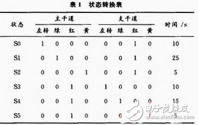
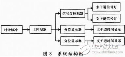
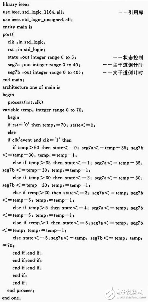
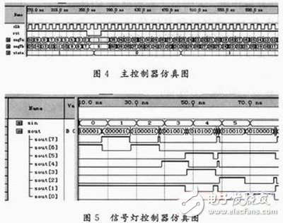
With the rapid development of the social economy, the traffic problems caused by the substantial increase in vehicles have become increasingly serious. Therefore, as an important part of the traffic supervision system, traffic lights play a huge role in coordinating the relationship between people, vehicles and roads. EDA (Electronic Design AutomaTIon) relies on a powerful computer to process design files completed by the hardware description language HDL (Hardware DescripTIon Langu age) for system logic description, and automatically realize the functions of the established electronic circuit system. A technology. The ultimate goal of electronic system design using EDA technology is to complete the design and implementation of an ApplicaTIon Specific Integrated Circuit (ASIC). As the final physical platform, ASIC centrally accommodates hardware entities that implement the specific functions and technical indicators of electronic application systems through EDA technology. Field Programmahie Gate Array (FPGA) is the mainstream device to realize this approach. It is characterized by great flexibility and versatility, high development efficiency, low cost, simple technical maintenance and good work reliability. There is a junction of a main road and a branch road forming a crossroad, the main road is east-west, and the main road is north-south. In order to ensure the safe and rapid passage of the vehicle, red, green and yellow three-color signal lights and left turn signals are arranged at each entrance of the intersection, as shown in Fig. 1. (1) When the green light of the main road is on, the red light of the main road is bright, and vice versa, the two are alternately allowed to pass. The main road is released for 40 s each time, and the main road is released for 30 s each time. Each time the green light is on, the first 10 s is the left turn light, and the last 5 s is the yellow light. The rest is a straight light. Analysis of the design requirements shows that the order of change of the traffic lights of the main and branch roads should be as shown in Figure 2. The state transition is shown in Table 1. According to the requirements, the system structure diagram design is shown in Figure 3. The clock pulse is generated by dividing the crystal pulse by a frequency divider. The main controller receives the clock signal and performs state transition according to this, and simultaneously outputs the time of each state. The signal light controller controls the main and branch road lights according to the state quantity generated by the main controller. Since the time signal output by the main controller is a real type, it is also necessary to design a quantile to convert it into two sets of BCD codes and send them to the digital tube display. In order to facilitate the system implementation, each module is designed in VHDL language. The main controller is a counter, the input signal is a second pulse, with 70 as a cycle, after counting to 1, when the next clock signal comes, the counter is reset, the next round of counting starts, and so on. The system reset signal reset resets the counter from any state to state S0 and restarts counting. Below is the VHDL file for the primary controller. Where clk and rst are clock and reset signals, state indicates the current state, seg7a, seg7b indicate the countdown time of the main and branch roads, and temp is the built-in variable. Each module is connected by Quartus II software, compiled and simulated, and each module can work normally. After the pins are allocated, the configuration file is downloaded to the KX_7C5TP FPGA development board, and the system runs normally, which verifies the correctness of the whole design. The simulation results are shown in Figure 4 and Figure 5. It can be seen from the above design that the design of the traffic signal control system using FPGA makes the designer's work limited to the use of software, that is, the hardware description language and EDA software are used to complete the design of the system hardware functions, which not only improves the design. The flexibility of the design also allows the designer to modify the fixed-cycle control time of the signal. LED Underwater light,Full colour underwater luminaires,Waterproof lighting underwater lamp Kindwin Technology (H.K.) Limited , https://www.ktlleds.com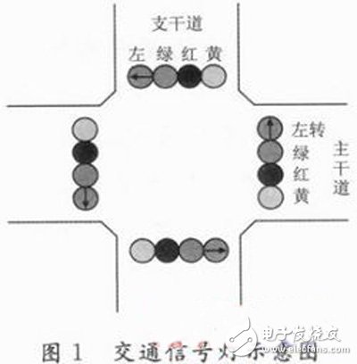
(2) A normal countdown display function can be realized.
(3) The overall clear function can be realized: the counter starts counting from the initial state, and the indicator of the corresponding state is on. 