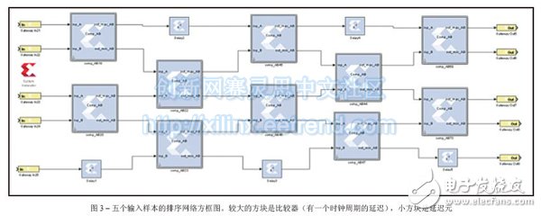
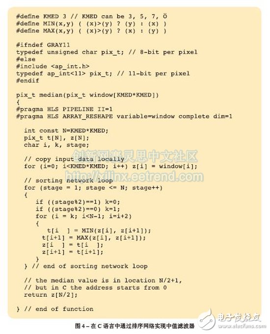
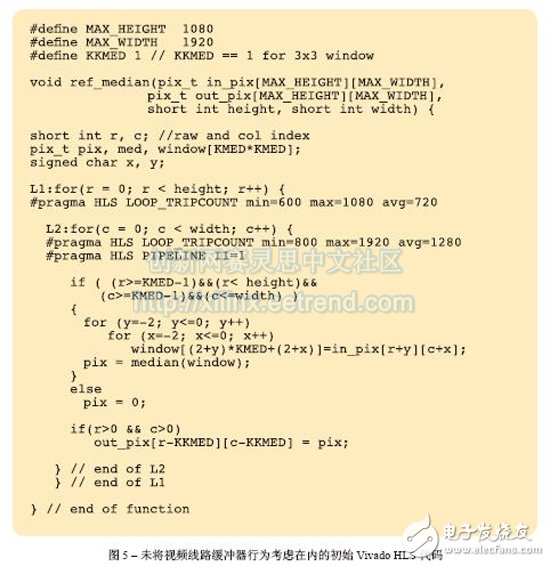
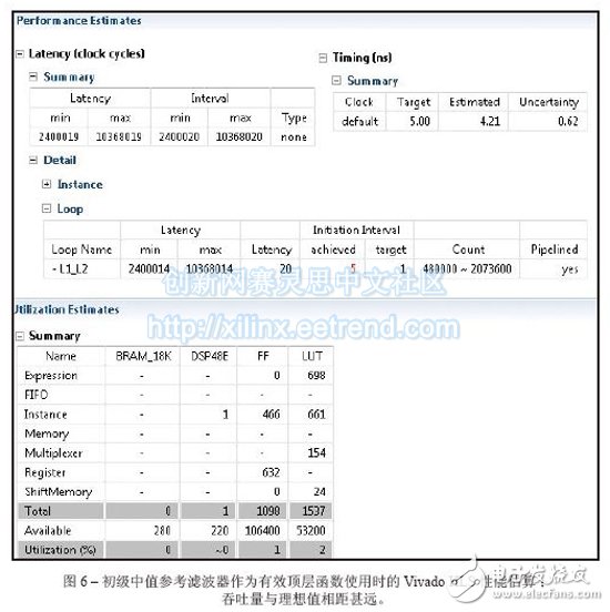
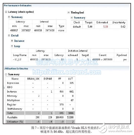
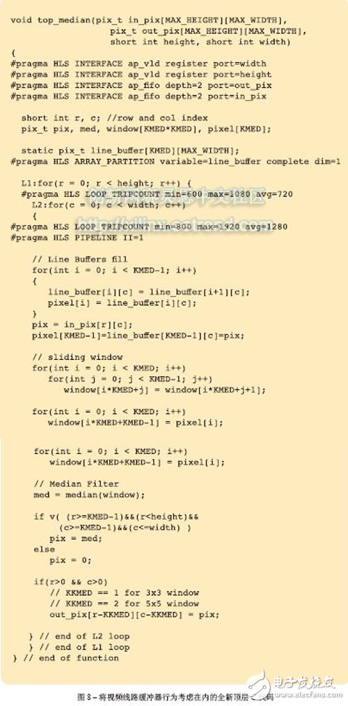
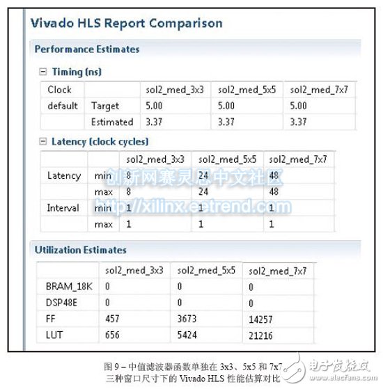
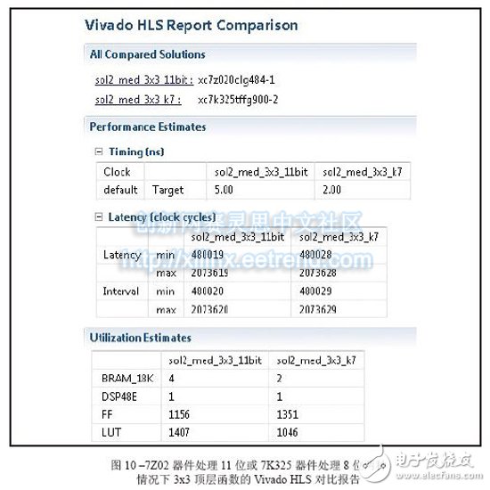
Vivado's high-level synthesis capabilities will help you design a better sorting network for embedded video applications. From cars to security systems to handheld devices, there are more and more applications that use embedded video capabilities today. Every new generation of products requires more features and better image quality. However, for some design teams, achieving high quality images is not easy. As a DSP design field application engineer at Xilinx, I am often asked questions about IP and efficient video filtering implementations. I've found that using the high-level synthesis (HLS) feature of the latest Vivado® design suite, it's easy to implement a high-performance median filtering method based on sorting networks in any Xilinx 7 Series All Programmable device. Before discussing this method in detail, let's review some of the challenges that designers face in terms of image integrity and the filtering techniques commonly used to solve them. Digital image noise mostly occurs in the process of acquiring or transmitting images by the system. For example, sensors and circuits of scanners or digital cameras can generate several types of irregular noise. Random bit errors or analog-to-digital converter errors in the communication channel can cause particularly cumbersome "pulse noise." This noise is often referred to as salt-and-pepper noise because it appears as a random white point or black dot on the image surface of the display, severely degrading image quality (Figure 1). To reduce image noise, video engineers often apply spatial filters to their designs. These filters replace or enhance poorly rendered pixels in the image with the high quality characteristics or values ​​of the pixels around the noise point. Spatial filters are mainly divided into linear and nonlinear. The most commonly used linear filter is called the averaging filter. It replaces each pixel value with the mean of the neighboring pixels. In this way, poorly rendered pixels can be improved based on the average of other pixels in the image. The averaging filter quickly removes image noise in a low-pass manner. However, this approach is often accompanied by side effects - blurring the edges of the overall image. In most cases, nonlinear filtering is better than linear averaging. Nonlinear filtering is particularly good at eliminating impulse noise. The most common nonlinear filter is the order statistical filter. The most popular nonlinear order statistical filter is the median filter. Median filters are widely used for video and image processing because they have excellent noise reduction and are much less blurred than linear smoothing filters of the same size. Similar to the mean filter, the median filter also analyzes each pixel in the image in turn and observes its neighboring pixels to determine if the pixel can represent its surrounding pixels. However, the median filter does not simply replace the pixel values ​​with the average of the surrounding pixels, but instead with the median of the surrounding pixel values. Since the median value must be the actual value of a neighboring pixel, the median filter does not create new virtual pixel values ​​when crossing the edge (avoiding the boundary blur effect of the mean filter). Therefore, the median filter does better than any other filter in retaining sharp edges. When calculating the median value, this filter first sorts all the pixel values ​​in the surrounding window in numerical order, and then replaces the pixels to be filtered with the intermediate pixel value (if the area to be calculated contains an even number of pixels, then the middle two are used. The average of the pixels). For example, suppose a 3x3 pixel window is centered on a pixel with a value of 229. The window value is as follows We can sort the pixels and get the order list as 5 39 57 61 83 164 204 225 229. The median is the pixel value in the middle, which is 83. This value is substituted for the initial value 229 in the output image. Figure 2 illustrates the effect of applying a 3x3 median filter to the noise input image of Figure 1. The larger the window around the pixel to be filtered, the more significant the filtering effect. The median filter has excellent noise reduction and is therefore widely used in the interpolation stage of scan rate video conversion systems, such as motion compensated interpolation programs that convert field rates from 50 Hz to 100 Hz for interlaced video signals, or Edge-oriented interpolator in interlaced to progressive conversion. For a more detailed introduction to the median filter, interested readers can refer to [1] and [2]. The key to using a median filter is to determine which sorting method to use to get a sorted list of pixels used to generate each output pixel. The sorting process requires a large amount of computation clock cycles. Currently, Xilinx offers a high level of integration in the Vivado Design Suite. I usually tell people that a simple and effective way to design a median filter in C can be based on the concept of sorting networks. We can use Vivado HLS [3] to get the real-time performance of the FPGA architecture of the Zynq®-7000 All Pro-grammable SoC [4]. In the following, we assume that the image format is 8 bits per pixel, 1,920 pixels per line, 1,080 lines per frame, and the frame rate is 60 Hz, so the minimum pixel rate is at least 124 MHz. However, in order to set some design difficulties, I will require the Vivado HLS tool to provide a target clock frequency of 200MHz. If you get a frequency value greater than 124MHz, the effect will be better (because the actual video signal also contains blank data, the clock rate is faster than the activity. The rate required by the pixel is high). What is a sorting network? Because sorting plays a key role in many applications, many articles in many scientific literature analyze the complexity and speed of well-known sorting methods, such as bubble sorting, hill sorting, merge sorting, and quick sorting. Fast sorting is the fastest sorting algorithm for large data sets [5], and bubble sorting is the simplest. In general, all of these techniques should run on a RISC CPU in the form of a software task, and only one comparison is performed at a time. Their workload is not constant, but depends on how much input data is partially ordered. For example, a set of N samples needs to be sorted, assuming that the computational complexity of fast sorting is N2, NlogN, and NlogN in the worst, general, and best cases, respectively. At the same time, the complexity of bubble sorting is N2, N2 and N, respectively. I have to admit that I have yet to find a unified view of such complexity numbers. But in all the articles I've read about this issue, it seems to agree with one point that computing the complexity of a sorting algorithm is not straightforward. This in itself seems to be the main reason for finding alternatives. When performing image processing, we need to get a definitive behavior on the sorting method to produce an output image with constant throughput. Therefore, none of the above algorithms can be an ideal alternative to FPGA designs using Vivado HLS. Sorting networks can achieve faster speeds by using side-by-side execution. The basic building block of the sorting network is the comparator. The comparator is a simple component that sorts the two data a and b, then outputs the maximum and minimum values ​​to the top and bottom output, respectively, and exchanges if necessary. The advantage of sorting networks for classical sorting algorithms is that the number of comparators is fixed for a given number of inputs. Therefore, the sorting network is easy to implement in FPGA hardware. Figure 3 illustrates a sorting network for five samples (generated using Xilinx System Generator [6]). It should be noted that the processing delay is exactly five clock cycles and is independent of the input sample value. Also note that the five parallel output signals on the right contain sorted data with a maximum at the top and a minimum at the bottom. Implementing a median filter through a sorting network in C is very simple, as shown in the code in Figure 4. The Vivado HLS instructions are embedded in the C language code itself (#pragma HLS). Vivado HLS requires only two optimization instructions to generate the best RTL code. The first is to pipeline the entire function with an initial interval (II) of 1, such that the output pixel rate is equal to the FPGA clock rate. The second step of optimization is to re-divide the pixel window into separate registers to synchronize parallel access to all data, thereby increasing bandwidth. The code segment in Figure 5 of the top-level function is the primary implementation of the median filter, which we will use as a reference. The innermost loop has been pipelined to produce an output pixel in any clock cycle. In order to generate the delay estimation report, we need to use the TRIPCOUNT instruction to inform the Vivado HLS compiler about the number of iterations that may occur in loops L1 and L2 because they are "uncontrolled". That is, suppose the design can handle image resolutions below the maximum allowable resolution of 1,920 x 1,080 pixels during runtime. The limit values ​​for these loops are the height and width of the image, both of which are compiled. It is unknown. In the C language code, the pixel window to be filtered can access different rows in the image. Therefore, the advantages of using memory locations to reduce storage bandwidth requirements are limited. Although Vivado HLS can synthesize the code, the throughput is not optimal, as shown in Figure 6. The initialization interval of loop L1_L2 (the result of the full expansion of the innermost loop L2, which is automatically executed by the HLS compiler) is five clock cycles instead of one, so the resulting output data rate cannot support real-time performance. This is also clarified from the maximum delay of the entire function. In a 5 nanosecond target clock cycle, the number of cycles used to calculate the output image is 10,368,020, which means that the frame rate is 19.2 Hz instead of 60 Hz. As detailed in reference [7], the Vivado HLS designer must explicitly write the behavior code of the video line buffer to the C language model used to generate the RTL because the HLS tool cannot automatically insert the new memory into the user code. in. The new top-level function C language code is shown in Figure 8. Since the current pixel coordinates (rows, columns) are displayed as in_pix[r][c], a sliding window needs to be created around the output pixels to be filtered in the coordinates (r-1, c-1). For a 3x3 window, the result is out_pix[r-1][c-1]. It should be noted that when the window size is 5x5 or 7x7, the output pixel coordinates are (r-2, c-2) and (r-3, c-3), respectively. The static array line_buffer can store the number of KMED video lines equal to the number of vertical samples in the median filter (the current number is 3); and due to the static C language keyword, the Vivado HLS compiler can automatically Map content to an FPGA dual port block RAM (BRAM) component. This allows real-time performance with very few HLS instructions. The innermost loop L2 needs to be pipelined to generate an output pixel in any clock cycle. The input and output image arrays in_pix and out_pix are mapped to the FIFO stream interface in the RTL. The line_buffer array is divided into multiple KMED independent arrays so that the Vivado HLS compiler maps each array into a separate dual port BRAM. Since there are more ports available, this increases the number of load/store operations (each dual port BRAM can perform two load or store operations per cycle). Figure 7 is a Vivado HLS performance estimation report. Currently, the maximum delay is 2,073,618 clock cycles. At an estimated clock period of 5.58 ns, we can get a frame rate of 86.4 Hz. This has exceeded our demand value! Loop L1_L2 gets II=1 as we would like it to. It should be noted that two BRAMs are required to store the KMED line buffer memory. Architectural exploration with high-level synthesis In my opinion, one of the best features of Vivado HLS is the ability to explore different design architectures and trade off performance by changing the tool's optimization instructions or the C code itself. Creative design freedom. Both modes of operation are very simple and not time consuming. What if you need a larger median filter window? For example, a window size of 5x5 instead of 3x3 is required. We just need to change the definition of KMED in C code from "3" to "5" and run Vivado HLS again. Figure 9 is an HLS comparison report obtained by synthesizing the median filter routines in three window sizes of 3x3, 5x5, and 7x7. In all three cases, the routines were fully pipelined (II = 1) and met the target clock cycle; the delays were 9, 25, and 49 clock cycles, respectively, in line with the expected performance of the sorted network. Obviously, as the total amount of data to be sorted increases from 9 to 25 or even 49, the resources used (trigger and lookup table) increase accordingly. Since the independent function is fully pipelined, the latency of the top-level function remains constant, and the clock frequency is slightly reduced when the window size is increased. So far we have only discussed this situation with the Zynq-7000 All Programmable SoC as the target device, but with Vivado HLS we can easily try different target devices in the same project. For example, if we choose the Kintex®-7 325T and combine the same 3x3 median filter design, the place and route resources used include two BRAMs, one DSP48E, 1,323 flip-flops, and 705 look-up tables (LUTs), clocks. The data rate is 403MHz; when using ZynqSoC devices, two BRAMs, one DSP48E, 751 flip-flops, and 653 lookup tables are required, with a clock and data rate of 205MHz. Finally, if we want to see the resource usage of the 3x3 median filter for processing 11-bit (rather than 8-bit) gray images per sample, we can change the definition of the pix_t data type by applying the ap_int C++ type, which allows The number of fixed points of any bit width. We can recompile the project simply by starting the C language preprocessing symbol GRAY11. In this case, the resource usage estimates on the ZynqSoC are four BRAMs, one DSP48E, 1,156 flip-flops, and 1,407 lookup tables. Figure 10 shows the combined estimation report for the last two cases. In just a few business days , we can also see how simple it is to generate timing and area estimates for median filters with different window sizes or even different numbers of bits/pixel. Especially when using a 3x3 (or 5x5) median filter, the RTL automatically generated by Vivado HLS only occupies a small area (-1 speed level) on the ZynqSoC device. After the placement and routing is completed, the FPGA clock frequency is 206. (5x5 version is 188) MHz and the effective data rate is 206 (or 188) MSPS. The total design time required to get these results is only five business days. Most of the time is spent building MATLAB® and C models instead of running the Vivado HLS tool itself; the latter takes less than two business days. Hd Screen Protector,High-Definition Screen Protector,Hd Clear Screen Protector,Transparent Screen Film Shenzhen TUOLI Electronic Technology Co., Ltd. , https://www.hydrogelprotectors.com
39 83 225
5 229 204
164 61 57 
Sorting is the process of reordering elements in an array in ascending or descending order. Sorting is one of the most important operations in many embedded computing systems. 