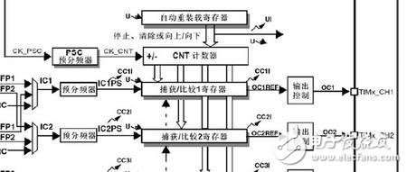
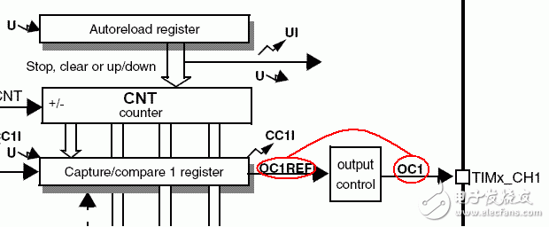
Adopt the channel 2 of timer 2, make PA1 output frequency 1K, PWM waveform of duty ratio 40, use PA8 to delay and take reverse led light, instruct the procedure to run It took half a day in the morning to become familiar with the stm32's PWM module. Use lunch time to debug the PWM function at noon. Of course, very simple things, perhaps many predecessors have estimated that they do not care. Today's biggest sigh is that online resources are a huge treasure trove. It is really fortunate that in this complex social environment, in an era full of selfishness and self-interest everywhere, many users on various websites and forums are constantly Open source atmosphere. Learning must communicate with others, and the internet provides such an excellent platform. Do not talk nonsense. Realize the function: Adopt the channel 2 of the timer 2, make the PA1 output frequency 1K, the PWM waveform of the duty ratio 40, use the PA8 to delay and invert the led lamp at will, instruct the procedure to run. First familiarize yourself with the PWM related part of the timer. Look at the picture the most understand In fact, PWM is a comparative function of the timer. The value in CNT is constantly ++. Once it is added to the CCRX register value, the corresponding action is generated. This is similar to the AVR microcontroller. In this case, we need to set the PWM frequency and PWM duty cycle to generate the required PWM signal. First of all, say the frequency of determination. Since the clock source of the general-purpose timer is PCLK1, and I like to use the default setting of the firmware library, the clock frequency of the timer is determined as follows: AHB (72MHz) → APB1 divider (default 2) → APB1 clock signal (36MHz) → frequency doubler (*2x) → general-purpose timer clock signal (72MHz). Why this is the case, there are detailed records in the RCC module learning record, not much to say. So the CK_PSC in the figure is 72MHz. The following information is also a search on the Internet, I will list: The STM32 PWM output has two modes, Mode 1 (PWM1) and Mode 2 (PWM2), determined by the OCxM bits in the TIMx_CCMRx register ("110" is Mode 1 and "111" is Mode 2). The difference between mode 1 and mode 2 is as follows: 110: PWM mode 1 - When counting up, channel 1 is inactive once TIMx_CNT = TIMx_CCR1 (OC1REF = 0), otherwise it is active (OC1REF = 1). 111: PWM mode 2 - When counting up, channel 1 is active once TIMx_CNT = TIMx_CCR1, otherwise it is an inactive level. From this point of view, Mode 1 and Mode 2 are exactly complementary and opposite to each other, so there is not much difference in application. I use mode one, so the following settings are set according to mode one. The period of the PWM is determined by the timer's automatic reload value and CNT count frequency. The CNT count clock is CK_PSC obtained by the divider PSC, so the CNT clock is the CK_PSC/div ratio. This division factor is determined in TIM_TimeBaseStructure.TIM_Prescaler. The value I set for Chengdu website design is 72, so the count frequency of CNT is CK_CNT frequency is 1MHz. The next step is to determine the automatic reload value of the timer. Because the CNT is automatically cleared each time it is added to the value of the ARR register, of course, the premise is that it is set to the up-counting mode, and that the period of the PWM is changed according to this overflow event. So the frequency of the PWM signal is determined by the value of ARR. The value I set is 1000-1, which means TIM_TimeBaseStructure.TIM_Period = 1000-1; therefore, the period of PWM is 1MHz/1000=1KHz. The next step is to determine the PWM duty cycle. Because the CNT will continuously compare with the CRRX value during the self-add to the ARR value, a match event will be generated once the two are equal, but it should be noted that CNT will not care about this and it will continue ++ until it equals ARR. The CRRX value I set to 400-1, then the duty cycle is then determined as 40%. Well, the following is the configuration of the library function. TIMER output PWM implementation steps 1. Set the RCC clock 2. Set up GPIO; 3. Set the relevant register of TIMx timer; 4. Set the PWM-related registers of the TIMx timer. The first is the declaration of the main function and the global variable, which is very simple and does not explain TIM_TimeBaseInitTypeDef TIM_TimeBaseStructure; TIM_OCInitTypeDef TimOCInitStructure; Int main(void) Rcc_cfg(); The following is the configuration of the IO port: Void gpio_cfg() GPIO_InitStructure.GPIO_Speed ​​= GPIO_Speed_50MHz; It should be noted here that the PWM output port should be configured to multiplex push-pull output, and I don't know why. The following is the TIM configuration function, the comments are very clear, do not explain: Void tim2_cfg() TIM_DeInit(TIM2); // Disable ARR preload buffer TIM_ARRPreloadConfig(TIM2, DISABLE); Next is the key PWM configuration function: Void pwm_cfg() { //Set the default value TIM_OCStructInit(&TimOCInitStructure); //PWM mode 1 output TimOCInitStructure.TIM_OCMode = TIM_OCMode_PWM1; // Set the duty cycle, duty cycle = (CCRx/ARR)*100% or (TIM_Pulse/TIM_Period)*100% TimOCInitStructure.TIM_Pulse = 400-1; //The TIM output is more polar TimOCInitStructure.TIM_OCPolarity = TIM_OCPolarity_High; //Enable output state TimOCInitStructure.TIM_OutputState = TIM_OutputState_Enable; // CH2 output of TIM2 TIM_OC2Init(TIM2, &TimOCInitStructure); // Set PWM output of TIM2 to enable TIM_CtrlPWMOutputs(TIM2,ENABLE); } The output compare unit structure of the stm32 firmware library and the time base unit of the timer are defined separately. However, the PWM mode only outputs a value of the comparison structure member TimOCInitStructure.TIM_OCMode. When this structure is filled, it is mapped again. To a timer, implemented with the TIM_OCXInit function, I used an X to illustrate more than one such function. In fact, the general timer of the stm32 has four channels, each channel corresponds to an initialization function, which is really entangled of! Finally, the PWM output function of this timer must also be enabled. The TIM_CtrlPWMOutputs(TIM2, ENABLE) function must take care that output is not output, indicating that TIM2 has more than one channel! Complex enough, tedious! The following is the structure prototype of the output comparison unit: Typedef struct Uint16_t TIM_OutputState; Uint16_t TIM_OutputNState; Uint16_t TIM_Pulse; Uint16_t TIM_OCPolarity; Uint16_t TIM_OCNPolarity; Uint16_t TIM_OCIdleState; Uint16_t TIM_OCNIdleState; The members that have not been added are advanced timers, and the general-purpose timers do not need to be controlled. There is also a TimOCInitStructure.TIM_OCPolarity member that needs attention. What does it do? Check the information on the Internet, as shown below: As mentioned before, pwm has pwm1 and pwm2 modes. These two modes can only be controlled until OCXREF. TIM_OCPolarity can control whether OC1 is directly equal to OCXREF or reverse polarity. OC1 is the final PWM signal. Here is an episode where I use an oscilloscope to measure the PWM signal and find that the signal is actually bipolar, and then change the TIM_OCPolarity, and then test, or bipolar, but only toppled. Really think that stm32 microcontroller can output two-polar PWM, after the oscilloscope to DC (before using the AC file), the waveform from the zero potential to move up and down. Pay attention later! Ethernet Switch,Internet Switches,Ethernet Splitter,Gigabit Managed Ethernet Switch Chinasky Electronics Co., Ltd. , https://www.chinacctvproducts.com
GPIO_InitTypeDef GPIO_InitStructure;
{
Gpio_cfg();
Tim2_cfg();
Pwm_cfg();
//
While (1)
{
GPIO_WriteBit(GPIOA, GPIO_Pin_8, Bit_SET);
Delay();
GPIO_WriteBit(GPIOA, GPIO_Pin_8, Bit_RESET);
Delay();
}
}
{
RCC_APB2PeriphClockCmd(RCC_APB2Periph_GPIOA, ENABLE);
GPIO_InitStructure.GPIO_Speed ​​= GPIO_Speed_50MHz;
GPIO_InitStructure.GPIO_Pin = GPIO_Pin_8;
GPIO_InitStructure.GPIO_Mode = GPIO_Mode_Out_PP;
GPIO_Init(GPIOA, &GPIO_InitStructure);
GPIO_InitStructure.GPIO_Pin = GPIO_Pin_1;
GPIO_InitStructure.GPIO_Mode = GPIO_Mode_AF_PP;
GPIO_Init(GPIOA, &GPIO_InitStructure);
}
{
RCC_APB1PeriphClockCmd(RCC_APB1Periph_TIM2,ENABLE);
TIM_InternalClockConfig(TIM2);
// The prescale factor is 72, so the counter clock is 72MHz/72 = 1MHz
TIM_TimeBaseStructure.TIM_Prescaler = 72;
// Set the clock division TIM_TimeBaseStructure.TIM_ClockDivision = TIM_CKD_DIV1;
// Set the counter mode to count up mode TIM_TimeBaseStructure.TIM_CounterMode = TIM_CounterMode_Up;
/ / Set the size of the count overflow, an update event is generated every 1000 counts TIM_TimeBaseStructure.TIM_Period = 1000-1;
//Apply the configuration to TIM2 TIM_TimeBaseInit(TIM2,&TIM_TimeBaseStructure);
TIM_Cmd(TIM2, ENABLE); //Enable TIMx Peripheral
}
{
Uint16_t TIM_OCMode;
} TIM_OCInitTypeDef; 