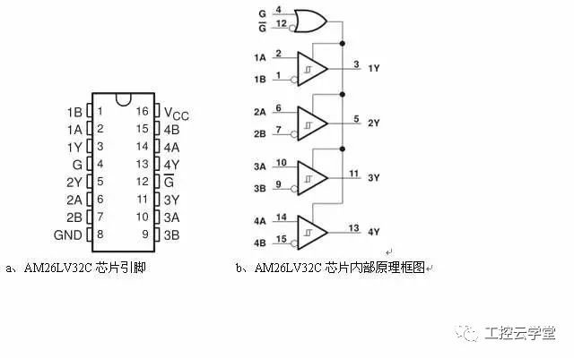
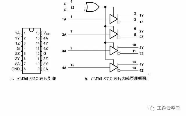
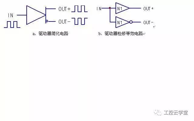
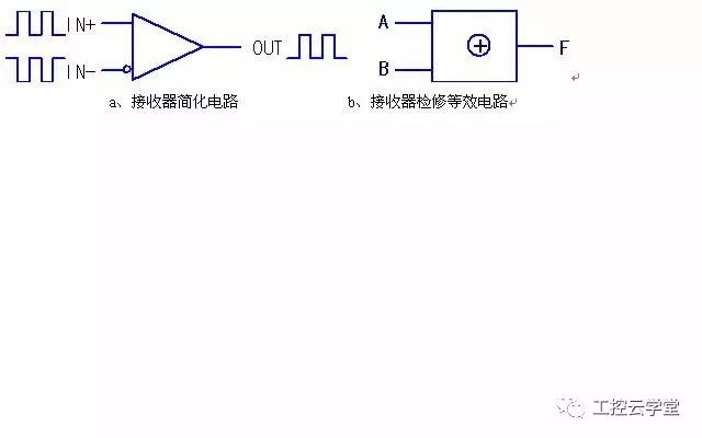
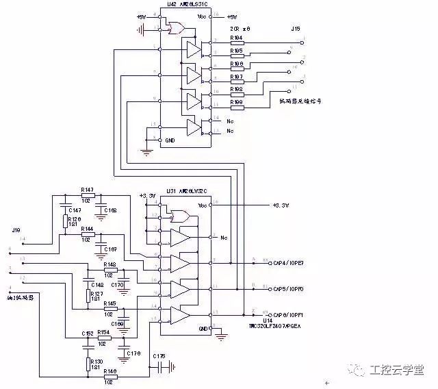
Think of communication circuits, naturally think of RS485, RS422 and other communication modes and circuit forms. As a hardware repairer, pay more attention to the latter. Some devices, such as inverters or servos, are used for signal transmission of a resolver or encoder, that is, PG card board or encoder interface circuit also uses similar devices. So what kind of device is this? If you leave the host computer or leave the source of the encoder, can you detect it? First, the device function Let the specific chip circuit speak first. See Figure 1 ~ Figure 3 circuit. Figure 1 RS485, RS422 transceiver chip Figure 2 AM26LV32C chip pin and internal block diagram Figure 3 AM26LS31C chip pin and internal block diagram Figure 1 shows a half-duplex/RS485, full-duplex/RS422 communication circuit, which contains two sets of receivers (or drivers) and receivers. The difference between the two sets of MAX485 circuits is to meet the half-duplex requirements. With enable control terminal. Figure 2 and Figure 3 show the frequent pairing. One is the four differential line driver, and the other is the four differential line receiver. In fact, it is still the splitting and expansion of the RS485 device. There is no difference in looking at one of the circuits. Second, the device definition The driver converts one serial pulse into two differential signals; the receiver turns the two differential signals into one serial pulse. Therefore, the role of this type of device is summarized in one sentence: a bidirectional converter of serial pulse and differential signal. Why is this? This is based on the huge power of the common mode interference caused by the transmission mode of the differential signal. One-two-two and one-of-a-kind conversion is nothing more than to improve the anti-interference ability of the transmission signal (line), otherwise one The direct transmission is complete. 1, the driver For the time being, we can ignore the "enable" control and the driver can be simplified to the circuit of Figure 4. Figure 4 Drive principle simplifies and repairs the equivalent circuit 1) The relationship between the input and output signals is shown in the circuit a of Figure 4, which is a one-in and two-out mode. 2) The circuit transmits digital signals, that is, 0 and 1. If it is powered by +5V, the static or immediate level of the circuit is not 5V or 0V. The two outputs must exhibit an inverse relationship. To the b equivalent circuit step, the circuit detection and good or bad judgment, almost no need to say. 2, the receiver The "Enable" control can still be ignored and the receiver can be simplified to the Figure 5 circuit. Figure 5 Receiver principle simplifies and repairs the equivalent circuit 1) The relationship between the input and output signals is shown in the circuit a of Figure 5, which is a two-in-one-out mode. 2) The circuit transmits digital signals, that is, 0 and 1. If it is powered by +5V, the static or immediate level of the circuit is not 5V or 0V. Although it is a differential mode, it is not appropriate to use a differential amplifier of an analog circuit because it is still a digital level signal. Here I can only use the XOR gate circuit to be equivalent - its style of discarding the same, it also meets the rules of circuit signal processing. Of course, I found the equivalent circuit, how to detect it, I don't have to talk nonsense. Third, maintenance examples Figure 6 encoder signal transmission circuit The above figure shows an example of a circuit of an AC servo drive. When a fault occurs in the encoder signal, it is necessary to detect and judge the circuit. The routine maintenance method is to check the closed loop mode of the motor and the encoder. Usually, the replacement method is used to remove the cause of the fault of the encoder itself. Independently overhaul the circuit, no need to close the loop (access encoder and motor) control, no pulse generator to give pulse signal, only need to prepare a DC adjustable power supply at hand, is already a universal signal generator ( Any signal transmission circuit can give a DC voltage signal for maintenance, which is later). Maintenance steps: 1, static judgment Measure the output terminals of pins 5, 11, and 13 of U31, all of which are 3.3V, and measure the output terminals of 2 and 3 pins of U42, which meet the level state of 2(1)3(0), and can judge that the circuit is static and normal; 2, dynamic measurement 1) Short the 4, 5, and 6 of the J19 terminal to the line A; short the 12, 13, and 14 to the line B. Adjust the regulated voltage output to 5V (limited to 10mA). 2) Line A is connected to the positive 5V signal, and line B is connected to the negative terminal of 5V. At this time, the output terminals of 5, 11, and 13 of U31 are measured as low level (about 0.5V), and it is judged that U31 is working normally; U42's 2, 3 pin and other output terminals become 2 (0) 3 (1) level state, and U42 can be judged to be normal. Convert the signal polarity of line A and line B, and the circuit maintains the static value. At this point, the overhaul of the encoder signal transmission circuit of Fig. 6 has ended. It’s really that simple, maybe things should have been that simple. It is often complicated by people who think it is complicated. I just want to find out the simple and definite maintenance mode that the circuit should have, and make an accurate judgment in a simple way. If the enable end of the circuit is disabled, we can temporarily "force it to the working state" for maintenance. Communication gateway series products can collect a variety of communication protocols Communication Gateway,Communication Smart Gateway,Wireless Communication Smart Gateway,Industrial Communication Gateway Jiangsu Sfere Electric Co., Ltd , https://www.elecnova-global.com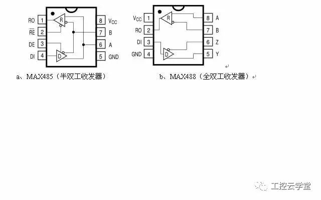
and upload data to small gateway equipment of cloud platform or local monitoring system; Gateway products in the field of industrial control support data analysis and calculation, automatic logic control, docking with multiple platforms, flexible web configuration and other functions; For the distributed system platform, it supports the secondary development and integration of various standard power protocols, Modbus industrial standards, MQTT protocol and non-standard protocols.