NXP's S32R274 is a 32-bit Power Architecture-based MCU for automotive and industrial radars. The security core uses an e200Z4 32-bit CPU, the computing core uses an e200Z7 32-bit CPU, and 2MB code flash with ECC (FMC flash memory) and tape are integrated. ECC's 1.5MB SRAM, radar interface including MIPI-CSI2 (4 data links), ΣΔ-ADC (4x 12-bit 10 MSps) and DAC (10 MSps), other interfaces including Zipwire, 2x SAR-ADC, 2x SPI, 2x I2C , 3x FlexCAN (incl. 2x CAN-FD), FlexrayTM, LINFlexD and Ethernet, Operating Temperature -40 to 150 ̊ CAEC-Q100 Grade 1. This article describes the main features of the S32R274, block diagram and series performance comparison table, and evaluation Board S32R274EVB main board and daughter board main features and circuit diagrams. Position Selector Switch,Rotary Selector Switch,Pole Rotary Switches,Ceramic Rotary Switch Foshan City Jiulong Machine Co., Ltd , https://www.jlthermostat.com
The S32R27 is a 32-bit Power Architecture based microcontroller for automoTIve and industrial radar applicaTIons. It offers >4x leap in performance per power vs the previous MPC577X products, and increases the level of integraTIon available to designers of next generaTIon automotive radar modules. Designed To address advanced radar signal processing capabilities and merge it with financial capabilities for generic software tasks and car bus interfacing. It meets the high performance computation demands desire required by modern beam-forming fast chirp modulation radar systems by offering unique signal processing acceleration together with powerful multi -core architecture.
S32R274 main features:
• On-chip modules available within the device include the following features:
• Safety core: Power Architecture? e200Z4 32-bit CPU with checker core
• Dual compute computation cores: Power Architecture® e200Z7 32-bit CPU
• 2 MB on-chip code flash (FMC flash) with ECC
• 1.5 MB on-chip SRAM with ECC
• RADAR processing
– Signal Processing Toolbox (SPT) for RADAR signalprocessing acceleration
– Cross Timing Engine (CTE) for precise timinggeneration and triggering
– Waveform generation module (WGM) for chirpramp generation
– 4x 12-bit ΣΔ-ADC with 10 MSps
– One DAC with 10 MSps
– MIPICSI2 interface to connect external ADCs
• Memory Protection
– Each core memory protection unit provides 24entries
– Data and instruction bus system memory protectionunit (SMPU) with 16 region descriptors each
– Register protection
• Clock Generation
– 40 MHz external crystal (XOSC)
– 16 MHz Internal oscillator (IRCOSC)
– Dual system PLL with one frequency modulated phase-locked loop (FMPLL)
– Low-jitter PLL to ΣΔ-ADC and DAC clock generation
• Functional Safety
– Enables up to ASIL-D applications
- FCCU for fault collection and fault handling
– MEMU for memory error management
– Safe eDMA controller
– Self-Test Control Unit (STCU2)
– Error Injection Module (EIM)
– On-chip voltage monitoring
– Clock Monitor Unit (CMU)
• Security
– Cryptographic Security Engine (CSE2)
– Supports censorship and life-cycle management
• Timers
– Two Periodic Interval Timers (PIT) with 32-bitcounter resolution
– Three System Timer Module (STM)
– Three Software Watchdog Timers (SWT)
– Two eTimer modules with 6 steps each
– One FlexPWM module for 12 PWM signals
• Communication Interfaces
– Two Serial Peripheral interface (SPI) modules
– One LINFlexD module
– Two inter-IC communication interface (I2C) modules
– One dual-channel FlexRay module with 128message buffers
– Three FlexCAN modules with configurable buffers -CAN FD optionally supported on 2 FlexCANmodules
– One ENET MAC supporting MII/RMII/RGMIIinterface
– ZipWire high-speed serial communication
• Debug Functionality
– 4-pin JTAG interface and Nexus/Aurora interface for serial high-speed tracing
– e200Z7 core and e200Z4 core: Nexus developmentinterface (NDI) per IEEE-ISTO 5001-2012 Class 3+
• Two analog-to-digital converters (SAR ADC)
– Each ADC supports up to 16 input channels
– Cross Trigger Unit (CTU)
• On-chip voltage DC/DC regulator for core clock (VREG)
• Two Temperature Sensors (TSENS)
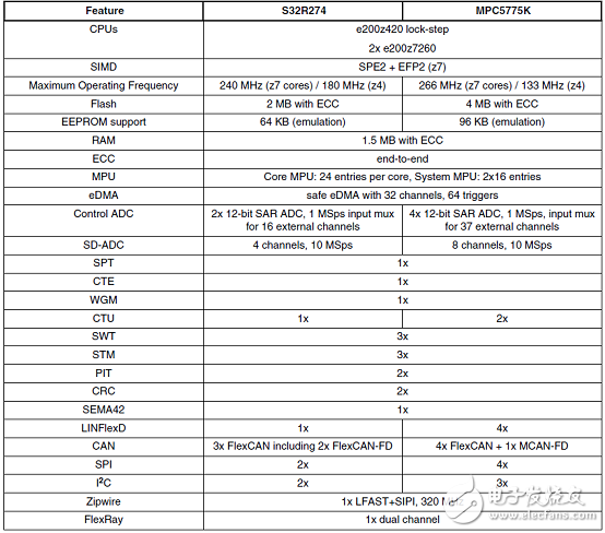
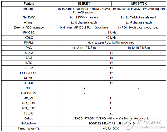
The following table provides a comparison of two devices S32R274 and MPC5775K.
This information is intended to provide an understanding of the range of functionality offered by this family. For full details of all of the family derivatives please contact your marketing representative.
S32R274 series product comparison table: 


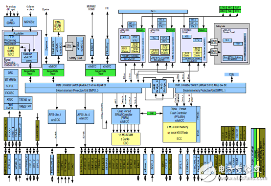
Figure 1. S32R274 block diagram