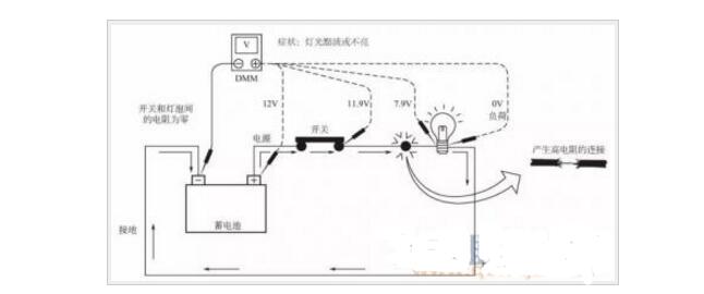
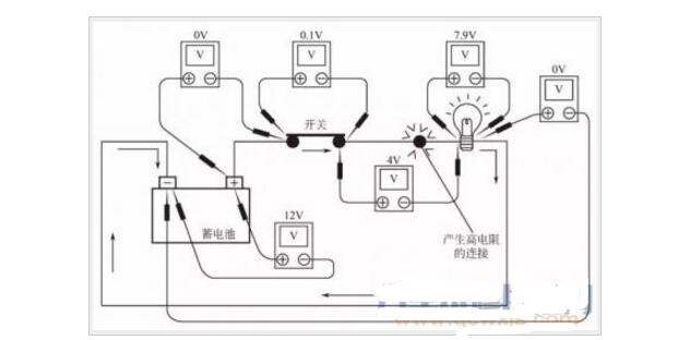
From the positive side of the power supply, return to the negative side of the power supply for a week along the external circuit. Take the negative pole of the power supply as the reference point. In this process, the load or the reverse voltage source is the voltage drop. The voltage source that meets the forward direction is the voltage rise. Select a bypass direction in a loop and give the reference direction of the voltage of a certain component "+" and "-". If the direction of detour is from "+" to "-", it is the voltage drop, if it is "-" To "+" is the voltage rise 1, the circuit loop, that is closed loop, each loop must be closed to be effective. 2, simply a loop that is a connected circuit, a circuit in the electronics must start from the positive through the entire circuit, of course, the circuit must have resistance, otherwise it will form a short circuit, after all the electrical back to the negative this forms A closed loop. However, the AC circuit starts from one phase and passes through the circuit to the other phase (industrial electricity) or back to the neutral or earth (civilian electricity). 1. A part of the voltage of a power supply will be consumed and reduced as part of the transmission voltage of a line or other component. The reduced part is the voltage drop of the line, measuring the voltage at the source's starting point and the voltage at the end point. The difference is the voltage drop. 2. Take a simple example. For example, if the substation output voltage is 220V and your home voltage is 215V, then the voltage drop from this substation to your home is 220V-215V=5V. Voltage drop detection is often used to find components or circuits that have excessive resistance. The voltage drop in the circuit is due to the resistance of the circuit during operation. The method of checking the wire is that when the resistance is measured with a digital multimeter, the reading temple is zero when the single wire is connected, indicating that the circuit is normal. However, single conductors cannot carry operating current when the circuit is operating. A single conductor will produce a high resistance to the current, which will produce a small voltage drop. Many of the following conditions may generate additional resistance: 1 The wire is too thin (for example, single wire). 2 switch contact corrosion. 3 Wires are loosely connected or tangled. When repairing, be sure to use a thick or thicker wire. Connect a digital multimeter across the component of the plug or line to be inspected. The positive pole of the voltmeter should be close to the power supply, and the negative pole should be close to the ground switch. Turn on the circuit to make the circuit work The Digital Universal Temple displays how much voltage the 'push' current passes through the circuit section. As shown above, there is an excessive 4.1V drop between battery and light bulb. The step method is the most effective way to check the pressure drop of a low pressure system (such as a computer control system). "Computer controlled systems, where the operating current of the circuit is very low, the system operation will be adversely affected by any resistance change in the system. The resistance change can be caused by poor contact, improper installation, wrong wire size or corrosion. Drop measurements to find parts or wires that have too much resistance. 1 Connect the digital multimeter and turn on the ignition switch. 2 Abnormal voltage drop means that there are parts or wires that need to be repaired. It can be seen from Figure 4-6 that the bad connection leads to a voltage of 4v. Voltage drop calculation method 1: â–³u%=I*R I=P/(1.732*U*COSθ)R=Ï*L/S P: power, U: voltage; COSθ power factor; Ï conductor resistivity, 0.018S for copper core cable: nominal cross-section of the cable, L: line length Allowable voltage drop in single phase: Vd=220Vx5%=11V Allowable voltage drop in three phases: Vd=380Vx5%=19V The second method of voltage drop calculation: â–³U%=K*I*L*V0 K: three-phase four-wire system K = 3 under the root number, single-phase K = 1; I: operating current or calculated current (A) L: line length; V0: voltage within the table (V/Am) Henan Yongrong Power Technology Co., Ltd , https://www.hnyongrongglobal.com


What is loop voltage rise or voltage drop