Model: SONY 40 inch LCD TV KDL-40V5500
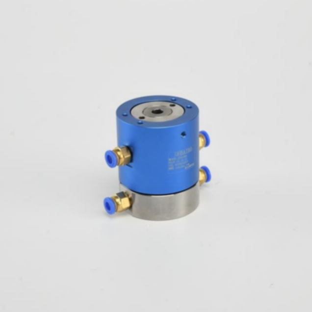
Conductive slip rings are one of the most popular types of electrical connectors. They consist of an insulating sleeve enclosing two metal contacts, with a small gap between them. When current is applied to the ring, it creates resistance between the contacts, which can be used to form a continuous circuit. They can be used in a wide range of applications, such as medical equipment, robotics, aerospace systems, and more. The construction of a conductive slip ring typically consists of two rotors (or rings), with each one containing a number of stationary contacts. When the rings rotate, the contacts move past each other and create an electrical connection.
In today's increasingly electronic world, the need for efficient and reliable power transmission is more important than ever. That's why more and more businesses are turning to slip rings as a means of transmitting power in a variety of applications. Slip rings are electrical connectors that allow current to flow continuously through a rotating assembly, making them ideal for use in devices that require uninterrupted power transmission, such as motors, generators, and wind turbines.
Oubaibo is a leading manufacturer and supplier of conductive slip rings, slip ring power connectors, and other related products. With years of experience in the industry, our products are known for their quality and durability. We offer a wide range of products to meet the needs of our customers, including standard slip rings, high voltage slip rings, military-grade slip rings, and many others.
Conductive Slip Ring,Slip Ring Power Connector,Electrical Slip Ring Assembly,Slip Ring Design Dongguan Oubaibo Technology Co., Ltd. , https://www.sliproubo.com
Fault: no picture after booting, no sound, no light,
After ten seconds, the indicator light turns from green light to red light, and the light flashes 6 times.
The red light flash is the fault code. The data is red flashing 6 times and the backlight is not working.
Knowing the position is easy, first find the backlight driver IC (LX1692FIDW), the 6-pin and 20-pin of the backlight driver IC are powered, the boot voltage is measured as 20-pin voltage 5V normal, and the 6-pin is delayed power supply (the voltage is supplied only after a few seconds of booting) ), measured the voltage of 6 feet is only about 0.5V, obviously not normal, the fault entry point starts from the IC6 foot, from 6 feet all the way to trace, chasing the cable between the power board and the motherboard, have not found the problem, trouble , the problem is on the motherboard? In order to find out whether the problem is on the motherboard, I disconnected the peripheral components of the backlight driver IC6 pin, and directly connected the 6-pin and 20-pin wires with the wires. The related data 6-pin and 20-pin circuit diagrams are connected, so it is so bold. After the line is connected, the backlight is turned on, the icon is also out, the signal is connected, the image and sound are normal, and the problem of the power board is eliminated. Then the problem is on the motherboard. A few resistors in series are found along the way. There is a capacitor, the first-level first-level voltage measurement, found that the voltage of the series resistance source is about 3.3V, haha, the fault range is reduced, and finally the inspection found that a capacitor is very suspicious, do not dare to take the capacitance measurement under the welding, cut with a blade The circuit related to the capacitor, the problem has finally been found, using the x100 resistance file to measure the leakage of this capacitor is about 2K, restore all circuits (except for the cut capacitor), start the test machine, the image appears, measured the voltage of 6 feet 3.3V, Then find a scrap board to disassemble a capacitor of the same size. As for the capacitor capacity, the leakage can not be measured, and there is no drawing, then it is not tangled, just look for it. The test machine was fine for a few days.
