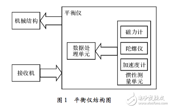
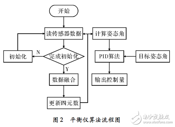
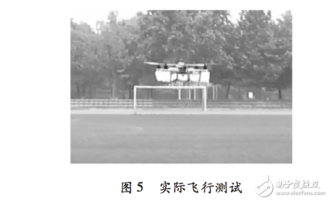
Small unmanned aerial vehicles are widely used in aerial photography, disaster relief, fire prevention, etc., but the operation of the drone is complicated, especially the control of the flight attitude is stable, the route is accurate and the landing is smooth, and the operation level of the ground personnel is relatively high. Operational problems are likely to cause flight accidents of drones. In severe cases, the aircraft body and on-board equipment will be damaged, and the safety of ground personnel and property will also be endangered. Therefore, a balancer is required to assist the ground operator in controlling the attitude and track of the aircraft. FPGA parallel processing of data, using the same algorithm, compared with the CPU, the calculation speed is high, the impact speed is fast, suitable for data-intensive, repetitive work. FPGAs are highly logically flexible, have good compatibility with various communication protocols, and can be formatted according to various control systems. FPGA architecture flight control has great advantages, but due to the difficulty of FPGA design, the development process is cumbersome, the development cycle is long, and the application and popularization of FPGA architecture flight control are affected. In this paper, a fast development method of FPGA architecture flight control based on Xllinx Vivado HLS tool is proposed for the above problems, and the method is applied to the design of quadrotor aircraft balancer. The balancer is used to improve the stability of the drone flight. The stability of the drone includes lateral stability, longitudinal stability and heading stability, which respectively indicate the ability of the drone to return to its original state in roll, pitch and heading. By using a balancer to assist ground personnel in maneuvering the drone, the drone's flight attitude can be precisely controlled. The balancer includes an inertial measurement unit: a three-axis accelerometer, a three-axis gyroscope, and a three-axis magnetometer for measuring the physical motion state of the drone; a data processing unit: a core of the balancer system for calculating the current posture of the drone and The control control mechanism performs structural adjustment of the drone attitude. The structure of the balancer is shown in Figure 1. The balancer algorithm is divided into a gesture solution algorithm and a control algorithm. The attitude calculation algorithm is used to obtain the current UAV flight attitude. The current attitude is represented by the elevation angle, the roll angle and the direction angle. The core of the attitude calculation algorithm is the quaternion method. The balancer software flow is shown in Figure 2. The processor and sensor are initialized after the system is powered on. The accelerometer is used to compensate the drift of the gyroscope, and the data fusion is performed to obtain the error quaternion. After the current quaternion is calculated, the current attitude angle is calculated. After decoding the remote control signal, the target attitude angle can be obtained, and together with the current attitude angle, the output of the control quantity is obtained by the PD algorithm. The advanced algorithms used in today's wireless, medical, military, and consumer applications are more complex than ever, and the most demanding RTL development teams are challenging to develop and validate their plans. Vivado Design Suite \Vivado's high-level synthesis brings C\C++ and System C specifications directly to Xllinx All Programmable devices, eliminating the need to manually create RTL, speeding up IP creation. Vivado's high-level integration supports ISE and Vivado design environments, enabling system engineers and design architects to create IP in a faster way. After exploring different design requirements and multiple microarchitectures, Vivado HLS (High-Level Synthesis) can directly convert C\C++ and System C to VHDL or Verilog's RTL level, which accelerates the implementation and verification of the design. Functional simulation can be performed in C language, which is an order of magnitude faster than VHDL and Verilog simulation. Vivado HLS provides designers and architects with a faster, more reliable method for high quality design. Through the above analysis, when using the Xllinx Vivado HLS kit, it is necessary to integrate the structure of the Xllinx Vivado HLS kit based on the flight control core code of the existing C language. After the function simulation, the advanced synthesis tool is converted to the corresponding IP. Core, generated in the EDK suite to generate the corresponding bitstream file. 3.1 C language code adjustment The C language platform is easy to debug. You can view the variable values ​​through online debugging. The data format is well supported and the code compilation is faster. You can use ARM to perform functional simulation on the flight control algorithm framework. After the flight control framework is verified, it is necessary to adjust the C language code, including the following aspects: 1. Organize the program structure of the flight control algorithm. The core code of the balancer is mainly divided into preprocessing of sensor data, attitude angle calculation, and control quantity calculation. Integrate these functions into a single function FC, using a uniform input and output variable. 2 Organize the input and output variables of the flight control algorithm. According to the data format requirements of the HLS tool, input variables use value transfer methods, output variables and input and output variables use pointer transfer methods. Input variables here include sensor data, remote control signal values, and control parameters. The output signal includes the aircraft's control signal, attitude angle, and a portion of the state value. 3 Adjust the data format of non-critical signals. At present, Xllinx Zynq series chips generally have dedicated DSP units for floating point processing, which have good support for floating point numbers. However, the number of DSP units is limited. For systems with strict requirements on response time, some methods of partial point operation can be used. For variables or key variables with high precision requirements, such as quaternion, use floating-point number calculation; for signals that are not demanding and have little influence on the system, such as remote control signal value, use fixed-point operation method. 3.2HLS use Create a project in HLS, select the correct target chip, add all C language files, and fill in the top-level function name of the algorithm in the Top FuncTIon of the project, in this case FC. Run C Syn thesis, warnings and errors for debugging prompts. The C language program of the flight control algorithm can be simulated by adding Testbench software. For example, when testing the attitude calculation function, it is necessary to use the pre-sampled sensor numerical verification algorithm to calculate whether the attitude value is accurate and the response is timely. The Testbench file is created, and the pre-stored sensor experimental data and the input and output variables corresponding to the FC function are defined. In the main function, the sensor data is sequentially sent to the FC function according to the sensor sampling order and the data format, and the experimental results are verified by using the SimulaTIon tool. Use the C Syn thesis tool to synthesize FC functions, which can be combined to view comprehensive reports, including expected usage of various resources. For example, in the design, it is found that LNT is expected to use more than the actual amount, and the usage rate is too high. Check where a large number of LUTs are used, and try to solve the problem by using module time-multiplexing. Open the C file corresponding to this function, select the corresponding function in the DirecTIve column, right click and select Insert DirecTIve in the pop-up dialog box, the Directive option is NLINE. You can also run the C language synthesis again by entering the script "set_directive_in line function name" to view the resource usage. After the code debugging is completed, use Export RTL, select the Pcore for EDK format, and generate the IP core corresponding to the flight control core algorithm. 3.3EDK configuration Add the generated IP core algorithm IP core path to the EDK and add this IP core to the corresponding project. Write the corresponding input and output IP cores. In the balancer design, you need to write the following modules: Remote control receiver signal decoding module: The remote control receiver signal used in this balancer adopts a 6-channel pulse width modulation signal with a period of about 22 ms, and the pulse width from 1 to 2 ms represents the signal amount of the channel signal from the smallest to the largest. After adding this template to the EDK project, write the corresponding MPD file and configure the corresponding input and output ports. The 6 channel signals are defined as inputs, and the width defaults to 2; the decoded 6 signals are defined as outputs, and the signal width is 32. After the .MPD file is configured, connect the port of this module to the signal corresponding to the flight control core module in the Ports tab. Sensor Read/Write Module: The sensor interfaces used in this balancer example are I*2C buses that share a set of bus interfaces. This module functions to initialize the sensor via the IC bus and read the sensor data for a certain sampling time. After adding this module to the EDK project, write the corresponding MPD file, the specific process is similar to the previous module. The SDA line of the IC bus is an input/output type. When writing an MPD file, note that the input, output, and gate are used to indicate the input and output exits. After the MPD file is configured, connect the port of the module to the signal corresponding to the flight control core module in the Ports tab. After completing the code writing and simulation test, a bitstream file is generated. To verify the validity of this method to generate an IP core, it is applied to the ZedBoard based on the Xilinx Zynq-7000 Extended Processing Platform (EPP). In order to visually compare the accuracy of the data, a serial port IP core is added to print the sensing data and the resolved attitude angle to the PC. The sensor data is sent to the core code of the original C language implementation. The attitude angle obtained by the simulation is compared with the attitude angle obtained in the FPGA, and the attitude angle is calculated accurately and the response is high. In order to visually compare the operation time, configure one FPGA output Busy signal to indicate the actual operation time. The Busy pin is asserted high at the beginning of each operation. The flight control system implemented in the ARM platform is also configured with a similar pin for outputting the actual operation of the flight control. Comparing the high-level width of the two pin output signals, as shown in Figure 3, the ARM platform needs to implement this algorithm for more than 1ms, while the FPGA platform only needs about 7μs for this algorithm, as shown in Figure 4, the hardware acceleration exceeds Two orders of magnitude have a big advantage. To verify the reliability of this method, the system was applied to a quadrotor. After the actual flight test, as shown in Figure 5, the aircraft is stable and suitable for actual flight test. As shown in Figure 5, the aircraft is stable in flight and suitable for a variety of visual range missions. The flight system has high reliability. This paper introduces a development method of small-scale UAV flight control system based on FPGA. With the Xilinx Vivado HLS tool, the flight control core code of the existing C language platform is converted into the IP core of the FPGA platform. The method is characterized by low development difficulty, simple process, short cycle, and the generated IP core running speed is increased by two orders of magnitude compared with the ARM platform, and the accuracy is not reduced. In this paper, the feasibility of this method is verified by an example of a simpler balancer. When dealing with more complex navigation algorithms and control algorithms, the FPGA platform will highlight its advantages of fast processing. This method can be based on FPGA. The flight control system has been widely used in the development process. In the subsequent improvement methods, more attention will be paid to the use of resources and the rational use of logical resources. references [2]Yu Shaolin. Research on Micro-miniature UAV Flight Control Computer Based on DSP+FPGA[D]. Hangzhou: Zhejiang University, 2011.
we are the best supplier in China to offer the networking tools including sort of insertion tools, impact and punch down tool (Ericsson punch down tool, Siemens punch down tool, Corning punch down tool and so on), crimping tool(RJ45 crimping tools, coaxial cable crimping tool, picabond ratchet crimper), cable stripper and cutter, Cable Tester and connector removal tool, and so on.
In short, we offer the networking tools for cutting and stripping coaxial cable, twist cable, and optical fiber. And professional compression crimping tool for different connectors, insertion tools for different modules .To save cost for customers, we have desired some tools with multi-function. So you can keep one tool instead of several different types. Meanwhile, for some coaxial cable crimping tool you can change the head to fit the cable specification yourself. It will make you lose weight on tool set but to finish your work perfectly.
Insertion Tool, Punch Tool, Cat 5 Cable Tester, Crimping Pliers, Cable Crimping Tool NINGBO YULIANG TELECOM MUNICATIONS EQUIPMENT CO.,LTD. , https://www.yltelecom.com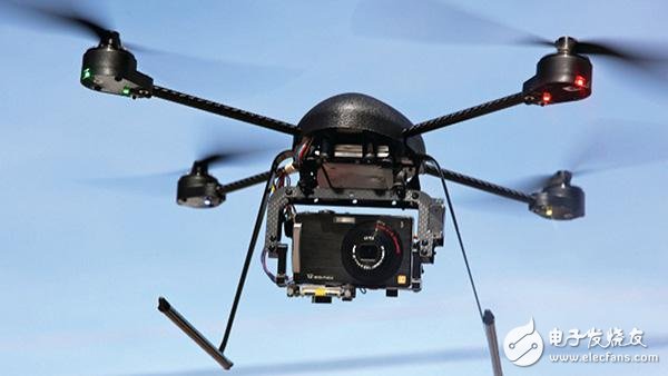
Mechanical actuator control drive module: At present, the control of small unmanned aerial motor and steering gear is mainly pulse width modulation signal. The function of this module is to convert the throttle, lift, roll and direction calculated by the flight control core module. It is the corresponding control signal and is output through the chip pin. After adding this module to the EDK project, write the corresponding MPD file and configure the corresponding input and output ports. For example, configure the port after the absorption by the flight control core module as the input, the width is 32 bits; output to the mechanical control mechanism The signal port is the output. The default is 1 bit. After the MPD file is configured, connect the port of the module to the signal corresponding to the flight control core module in the Ports tab. 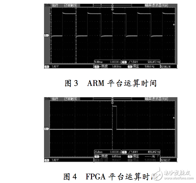
[1] Huo Xinyu. On the research of drones in forest fire prevention monitoring [J]. Technology and Innovation, 2014 (7): 128-130.
[3] Zhang Pengyi.Application of Infrared Sensor in UAV Attitude Balance System[J].Electronics Optics & Control,2007,14(6):170-172.
[4] Zhang Tianguang. Strapdown Inertial Navigation Technology [M]. Beijing: National Defence Industry Press, 2007.
[5] Xu Yu. Research on Micro-miniature UAV Flight Control Platform and Attitude Fusion Algorithm [D]. Hangzhou: Zhejiang University, 2008.
[6] Qin Yongyuan. Inertial Navigation [M]. Beijing: Science Press, 2006.
[7] Hu Shousong. Principle of Automatic Control [M]. Beijing: Science Press, 2001.
[8] Xilinx.Vivado design suite user guide[M].San Jose: Xilinx, 2013.
[9] Xilinx.Vivado design suite tutorial[M].San Jose: Xilinx, 2013.
[10] He Bin. Xilinx FPGA Design Authoritative Guide Vivado Integrated Design Environment [M]. Beijing: Tsinghua University Press, 2014. 