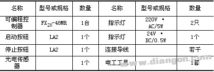
1. The equipment, tools and materials required for the project are shown in Table 1. Table 1 Equipment, tools and materials required for the project
Draw-wire sensors of the wire sensor series measure with high linearity across the entire measuring range and are used for distance and position measurements of 100mm up to 20,000mm. Draw-wire sensors from LANDER are ideal for integration and subsequent assembly in serial OEM applications, e.g., in medical devices, lifts, conveyors and automotive engineering.
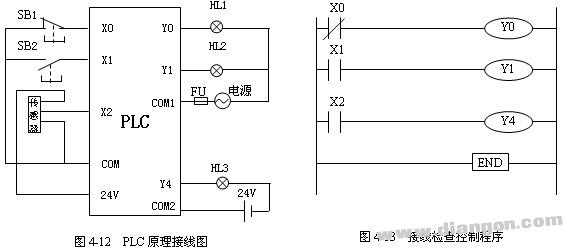
Linear Encoder,Digital Linear Encoder,Draw Wire Sensor,1500Mm Linear Encoder Jilin Lander Intelligent Technology Co., Ltd , https://www.jllandertech.com Second, the training content 1, project description This project requires the completion of the following: (1) according to the terminal diagram of FX 2N -48MR and plc control schematic diagram, draw the wiring diagram of the PLC system; (2) complete PLC wiring; (3) The PLC program provided is written into the PLC by using a computer or a handheld programmer; (4) The operation is performed according to the operation of the PLC system according to the step operation.
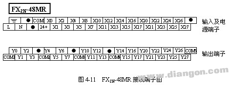
 2. Wiring diagram The input and output terminals of the FX 2N -48MR are shown in Figure 4-11. The sensor uses a three-wire proximity switch, which can be capacitive, inductive or photoelectric. In the description of the operation, a photoelectric switch is taken as an example. Figure 4-12 shows the wiring of the PLC. 3. Basic operation requirements Enter the control program according to Figure 4-13. When the SB1 button is pressed, the indicator light 1 is on. When it is released, the indicator light is off. The LED indicator on the PLC panel is the opposite. When the SB2 button is pressed, the indicator light 2 is on. When it is released, the indicator light is off. The LED indicator on the PLC panel is synchronized with it. A bright object approaches the photoelectric switch, and the indicator light 3 is illuminated.