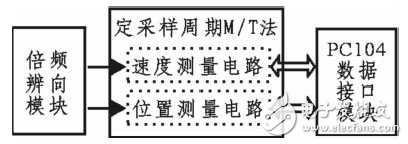
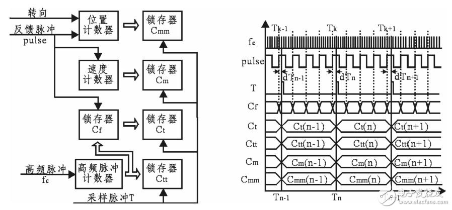
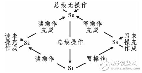
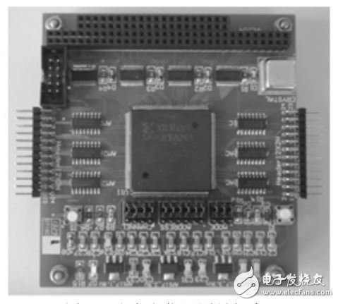
Aiming at the problem that the incremental speed measurement algorithm of the incremental photoelectric encoder M/T method is too long and the accuracy of the position measurement algorithm is not high, this paper designs and implements the speed and position measurement board based on the fixed sampling period M/T method. The Xilinx XC3S400 FPGA is used to design the core control chip, and the PC104 bus interface is designed to realize the data communication between the board and the controller. The board receives the feedback pulse of the photoelectric encoder to obtain the speed and position parameters, and transmits the data to the controller through the PC104 bus interface. Experiments show that the minimum sampling time of the board reaches 1ms, and the position measurement accuracy can reach 5 & TImes; 10-5. Incremental photoelectric encoders are widely used as servos in speed and position sensors. Theoretically, the frequency of the photoelectric encoder feedback pulse corresponds to the measured shaft speed, and the accumulated value of the feedback pulse number corresponds to the position information. There are three kinds of classical speed measurement methods: M method, T method and M/T method. Among them, the M method calculates the current speed by counting the number of feedback pulses of the photoelectric encoder in a fixed time interval, which is suitable for high-speed occasions; The pulse measures the time interval of the adjacent feedback pulse to calculate the current speed, which is suitable for low speed applications; the M/T method not only measures the incremental value of the feedback pulse in a fixed time interval, but also counts the number of high frequency pulses during that time. Although the M/T method overcomes the shortcomings of the M method and the T method with limited speed range, it has high resolution and low speed measurement error in both high speed and low speed segments, but there are problems such as low speed sampling time being too long. The classical position measurement method increases or decreases the feedback pulse according to the positive and negative of the steering, and then multiplies the count value by the pulse equivalent K to obtain the current position information. It can be seen that the measurement accuracy depends on the pulse equivalent. Based on the fixed sampling period M/T method, this paper solves the problem that the classical M/T method has a long detection time and ensures that data can be sampled every fixed period. In addition, the algorithm makes full use of the position information and time information of the feedback pulse to obtain more accurate position information than a pulse equivalent K. In this paper, the FPGA design is used to realize the fixed sampling period M/T method, and the PC104 bus interface is designed to meet the requirements of data communication between the board and the controller. The speed and position measurement board receives the feedback pulse signal of the photoelectric encoder, converts it into a single-ended signal through a differential circuit to eliminate common mode interference, and then obtains the speed and position parameters in the FPGA for the pulse processing, and finally passes the parameters through the PC104 data interface. Passed to the controller. The speed and position measurement boards except the differential circuit are implemented by FPGA design (as shown in Figure 1), so FPGA is the core chip of this board. The speed and position measurement board mainly includes a multiplier discrimination module, a fixed sampling period M/T method module and a PC104 data interface module. Figure 1: FPGA block diagram 1. 1 Multiplier Discrimination Module The output feedback pulse of the photoelectric encoder includes A and B signals with a phase difference of 90° and a zero pulse Z. The phase relationship between A and B marks the steering of the measured axis, that is, the A phase leads the phase B by 90° to indicate forward rotation, the lag 90° indicates reverse rotation, and the Z pulse acts as the reference zero point. In a cycle, the relative positions of the two signals A and B are changed four times, that is, forward rotation A and B are cyclically outputted according to 00-10-11-01, and the inversion follows the law of 00-01-11-10. The multi-frequency discrimination module outputs the quadruple frequency and direction signals by detecting the state changes of the A and B signals, which not only improves the accuracy of the speed and position measurement, but also acts as an anti-interference. 1.2 Fixed sampling period M/T method module sampling period M/T method module is divided into two parts: speed measurement circuit and position measurement circuit. Figure 2 shows the hardware principle and timing diagram of the algorithm. The sampling period M/T method is designed for the high-frequency pulse fc two-stage latching to ensure that the actual detection starting point Tk leads the sampling period Tn, which solves the problem that the M/T method detects too long at low speed, ensuring each Data can be successfully acquired during the sampling period. Figure 2 Scheduling cycle FPGA principle and timing diagram The speed measurement hardware circuit is composed of a speed counter and its data latch Cm, and a high frequency pulse counter and its two-stage data latches Cf and Ct; wherein the speed latch Cm and the high frequency pulse latch Ct are sampled pulses Trigger, the auxiliary high frequency pulse latch Cf is triggered by the feedback pulse. The differential speed Cm and the high-frequency pulse increment Ct in the current period Tn are obtained by differential processing, and the frequency of the high-frequency pulse is fc, and the pulse equivalent is K, then the calculated rotational speed is: The position measurement hardware circuit also employs a two-stage latch design of high frequency pulses, in addition to a position counter and its data latch Cmm, and an auxiliary position latch Ctt. It can be seen from Fig. 2 that the position change corresponding to the two time differences dTn-1 and dTn is less than one pulse equivalent K, and the position measurement algorithm adds the position change within the above time difference to the position information, thereby improving the resolution and accuracy of the position measurement. . dTn is obtained by the differential current period auxiliary position latch Ctt and the pulse latch Ct, and then dTn is multiplied by the velocity value Vn to obtain a position change. The position latch Cmm takes the change value of the feedback pulse, and the position change in dTn-1 and dTn can calculate the accurate position information. The Verilog design is used to implement each module based on the overall design of the speed and position measurement board. 2.1 Multiplier Discrimination Module This module detects the level of A and B on the rising edge of the FPGA system clock clk and compares it with the state recorded by the previous clk: when the state changes in accordance with 00-10, 10-11, 11-01, 01-00, it indicates that A leads the B phase by 90°, and A or B generates an edge jump. At this time, the photoelectric encoder rotates to set the 1 direction signal, and simultaneously outputs a counting pulse, so that 4 will be generated in one cycle. The counting pulse realizes four times frequency; when the change corresponds to 00-01, 01-11, 11-10, 10-00, the flag A lags the B phase by 90°, and the photoelectric encoder reverses to clear the direction signal, and outputs a signal. Counting pulse; when the change meets 00-00, 01-01, 10-10, 11-11, it indicates that the photoelectric encoder is in the commutation stage, or corresponds to the intermediate state of forward and reverse, at this time, the direction signal is maintained and the count is not output. Pulse; when the change is 00-11, 01-10, 10-01, 11-00, it indicates that the A and B signals are disturbed and the wrong state is reversed. At this time, the direction signal is maintained and the counting pulse is not output. Anti-interference purpose. 2.2 Fixed sampling period M/T method module analysis The sampling period M/T method module knows that it mainly consists of a counter and a latch, wherein the counter counts the number of pulses, and the obtained count value is stored in the latch. The data interface module reads. The counter can be subdivided into an up counter and a reversible counter, depending on the way of counting. The high frequency pulse counter and the speed counter both use up counting, and add 1 count value when detecting that the counting pulse is valid. The position counter adopts the method of reversible counting, and the counting pulse is determined to increase or decrease by the direction pulse when the counting pulse is valid. Since the feedback pulse count of the incremental photoelectric encoder can only obtain the relative position of the turntable, the value stored in the counter should be corrected, that is, reset to zero, before the counter is powered off or the control system is powered on. In order to achieve zeroing operation, the counter needs to have functions such as clearing and setting in addition to reversible counting. When the sampling pulse T is valid, the latch latches the current data for reading by the interface circuit, wherein the sampling period depends on the frequency at which the controller reads the speed and position. Considering the security of data reading, the controller must first complete the data latching operation of each latch before the controller reads the operation, that is, the latching operation of the latch is triggered by the sampling pulse generated by the controller to the write signal of the board. This module is designed with four double-word latches for temporary storage speed and position parameters, thus opening up four double-word I/O address spaces. The controller reads the I/O address to realize the reading of the latch data, and the write operation provides signals such as clearing, setting, and sampling pulses for the board. 2.3 PC104 data interface module In the PC104 system, to prevent I/O address conflicts, each module must have a separate base address. The speed and position measurement board is decoded using a 10-bit address, and the base address is set by the base address jumper on the board. The PC104 data interface uses I/O read/write mode for communication, and the state machine is designed to implement this module as shown in Figure 3. S0 is an idle state, and this state is an initial state. Once the controller operates the board, it enters the S1 state. The S1 state records the controller's address, data, and control signals, and determines the type of operation of the controller. If the read operation enters the S2 state, if it is a write operation, it enters the S3 state. In the S2 state, the data of the corresponding address is given to the data line to complete the read operation. In the S3 state, data is written to the corresponding address to complete the write operation. After the read operation or the write operation is completed, the state returns to S0 again, waiting for the controller to read and write next time. Figure 3: PC104 Interface State Machine The effect of each state will be described below in conjunction with the signal of PC104. The S0 state detection address enable signal AEN, when AEN is valid and the upper bit of the address signal SA coincides with the base address, indicating that the controller operates on the board, the S1 state is activated. The S1 state records the lower 4 bits of the address signal SA and the data signal SD, and judges whether the read signal IOR or the write signal IOW is valid. When the IOR is valid, the current read operation enters the S2 state, and the IOW valid indicates that the current write operation enters the S3 state. The S2 state branches the address to determine the address of the data to be read, and outputs the data corresponding to the address to complete the read operation. The S3 state writes data to the corresponding address to complete the write operation. The function of each module is realized by ISE software programming, and it is simulated by ModelSim. Figure 4 shows the simulation results. As can be seen from the figure, the input A and B signals simulate three states of forward rotation, reverse rotation and interference. Four pulses are output every cycle under forward and reverse rotation, and the forward direction signal is set to 1, and the reverse direction is cleared. The count pulse is not output under the interference signal, and the direction signal remains unchanged. The speed counter counts when the counting pulse is valid, and the position counter counts up and down according to the direction signal, and the speed latch Cm and the position latch Cmm latch the speed and the position value when the sampling period is valid. The auxiliary high frequency pulse latch Cf and the high frequency pulse latch Ct perform two-stage latching on the high frequency pulse to ensure that the actual sampling point leads the sampling period, and the data can be sampled every cycle. Figure 4: Simulation diagram Figure 5: Speed ​​and position measurement board The design completed speed and position measurement board is shown in Figure 5. The FPGA uses Xilinx's XC3S400, and the controller part uses Shengbo's SAT-1040 board. Using a 36,000-line incremental optical encoder, the high-frequency pulse is provided by a 40 MHz crystal oscillator with a minimum sampling period of 1 ms. The speed and position measurement accuracy in the measurement range are 3x10⁻⁵ and 5x10⁻⁵, respectively. In this paper, FPGA is used as the core control chip to realize the speed and position measurement board. It uses the M/T method of the fixed sampling period to process the feedback pulse processing of the photoelectric encoder to obtain the parameters characterizing the speed and position. The data is transmitted through the PC104 bus interface. Passed to the controller to calculate accurate speed and position information. The whole design is completed in the FPGA, so the hardware structure is introduced, the reliability is strong, and the anti-interference ability is strong; the minimum sampling time of the board reaches 1 ms, ensuring that reliable data can be sampled under each cycle, and the position measurement accuracy is improved to 5x10⁻⁵.
Yixing Futao Metal Structural Unit Co. Ltd. is com manded of Jiangsu Futao Group.
High Mast Lighting,High Mast Lighting Pole,Led High Mast Lighting,High Mast Street Lights,30m High Mast YIXING FUTAO METAL STRUCTURAL UNIT CO.,LTD( YIXING HONGSHENGYUAN ELECTRIC POWER FACILITIES CO.,LTD.) , https://www.chinasteelpole.com

Vn=KxfcxCm/Ct
dTn=(Ctt(n)-Ct(n))/fc
S=KxCmm+VnxdTn-Vn-1xdTn-1
The PC104 bus is an industrial control bus defined for embedded control. It has the advantages of small size structure, excellent shock-proof stack connection, low-power bus driver, etc. It is widely used in the development of airborne equipment. In addition, it is an 8-bit and 16-bit compatible bus. This module adopts 8-bit bus mode and uses the following bus signals to complete communication design: SD7~SD0: data signal; SA9~SA0: address signal; AEN: address enable signal ; IOR: I / O read signal; IOW: I / O write signal; power signal. 


we provide 30m High mast lighting poles and they are designed to accommodate a number of lowering device manufacturers` equipment. High mast poles can be easily galvanized or painted for even greater versatility.
It is located in the beach of scenic and rich Taihu Yixing with good transport service.
The company is well equipped with advanced manufacturing facilities.
We own a large-sized numerical control hydraulic pressure folding machine with once folding length 16,000mm and the thickness 2-25mm.
We also equipped with a series of numerical control conveyor systems of flattening, cutting, folding and auto-welding, we could manufacture all kinds of steel poles and steel towers.
Our main products: high & medium mast lighting, road lighting, power poles, sight lamps, courtyard lamps, lawn lamps, traffic signal poles, monitor poles, microwave communication poles, etc. Our manufacturing process has been ISO9001 certified and we were honored with the title of the AAA grade certificate of goodwill.
Presently 95% of our products are far exported to Europe, America, Middle East, and Southeast Asia, and have enjoyed great reputation from our customers.
So we know the demand of different countries and different customers.
We are greatly honored to invite you to visit our factory and cheerfully look forward to cooperating with you.